Samsung Galaxy Book Pro 15" Front Case Replacement
ID: 154950
Description: Use this guide to replace the front case in...
Steps:
- Before you begin, power down your laptop and unplug it.
- There are two kinds of rubber feet along the top and bottom of the rear case. Keep track of their position as you remove them.
- Insert an opening pick between the rubber foot and the rear case.
- Pry up with the opening pick to release the clips securing the foot.
- Remove the foot.
- Repeat this procedure for the three remaining feet.
- During reassembly, press the feet into their correct slot to reinsert them. Mismatched feet won't fit correctly.
- Use a Phillips screwdriver to remove the four 4.5 mm-long screws securing the rear case.
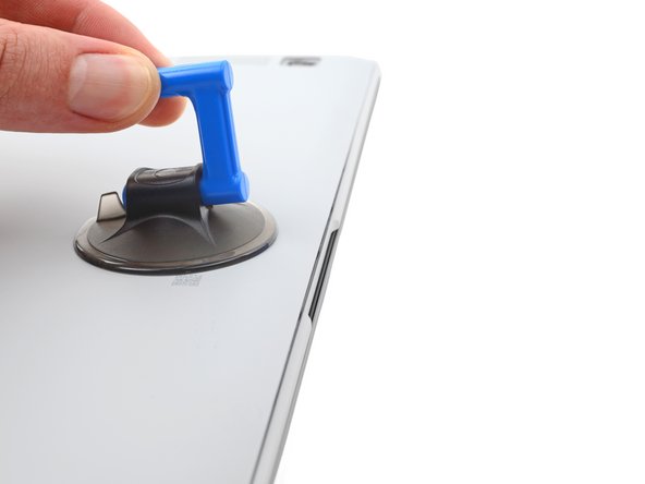
- Apply a suction cup to the rear case, as close to the center of the bottom edge as possible.
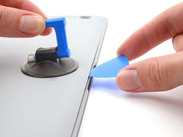
- Pull up on the suction cup with strong, steady force to create a gap between the rear case and the frame.
- Insert an opening pick into the gap.
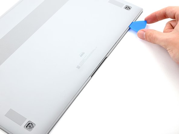
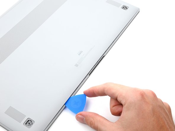
- Slide the pick along the bottom edge of the rear case to release its plastic clips.
- Repeat this process for the left and right edges, but stop before reaching the top edge.
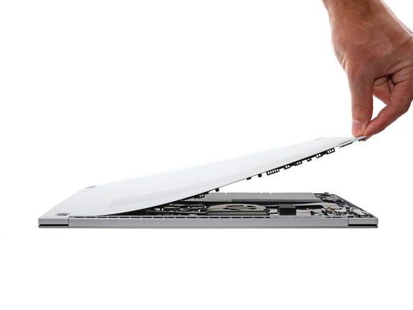
- The top edge of the rear case is lightly adhered to the frame.
- Pull the top of the rear case away from the frame to separate the adhesive and release the remaining clips.
- If you're having trouble separating the adhesive, use an iOpener, hair dryer, or heat gun to soften it.
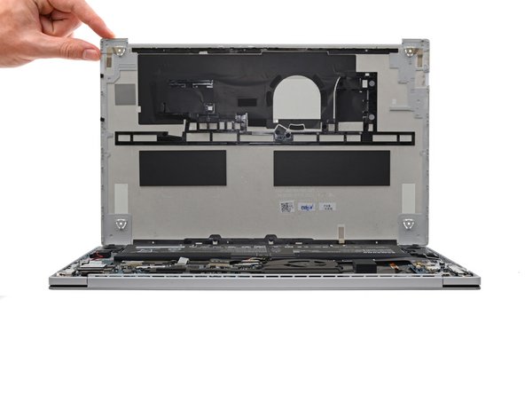
- Remove the rear case.
- During reassembly, perform the following:
- If you're using a using a genuine Samsung replacement rear case, be sure to peel off any adhesive liners from the rear case before securing the top edge's clips.
- If you're reusing your rear case, you can use some pre-cut adhesive to re-adhere the top edge if your existing adhesive is no longer sticky.
- This is a good point to power on your laptop and test all functions before sealing it up. Be sure to power your laptop back down completely before you continue working.
- Insert a spudger between the frame and the bottom of the battery cable connector.
- Pry up and disconnect the battery cable connector.
- If your Galaxy Book doesn't have an M.2 2280 SSD, skip the next two steps.
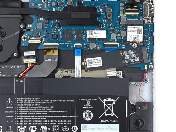
- Use a Phillips screwdriver to remove the 3.5 mm-long screw securing the SSD.
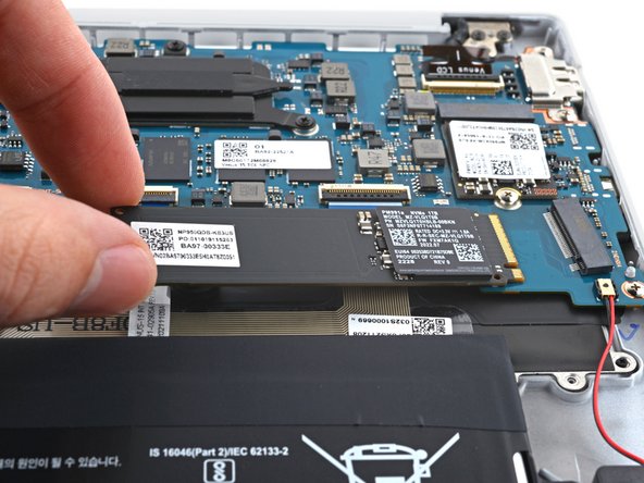
- Lift the free end of the SSD up slightly and pull the SSD straight out of its socket on the motherboard.
- Use a Phillips screwdriver to remove the four 4.5 mm-long screws securing the battery.
- Take care not to puncture the battery with your screwdriver—a punctured battery may leak dangerous chemicals or cause a fire.
- Lift the battery straight out of the frame and remove it.
- Use a spudger to pry up and disconnect the bottom left speaker connector from the daughterboard.
- Use a spudger to gently pry up the locking flap on the daughterboard ZIF connector for the interconnect cable.
- Disconnect the interconnect cable by sliding it out from its socket on the daughterboard.
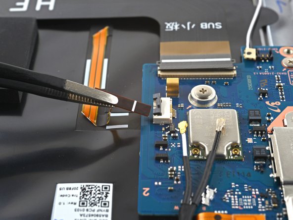
- Use a spudger to gently pry up the locking flap on the ZIF connector for the keyboard backlight cable.
- Disconnect the keyboard backlight cable by sliding it out from its socket on the daughterboard.
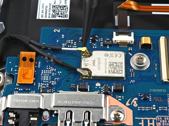
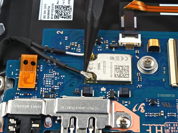
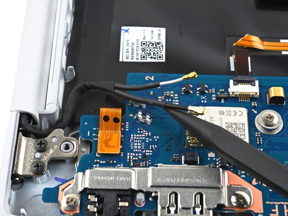
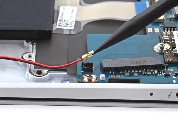
- Use the tip of a spudger to pry up and disconnect the two WLAN antenna cables.
- Pry under the bottom of the cable's metal head and not the cable itself.
- During reassembly, these can be tricky to reconnect. One at a time, hold each connector in place over its socket and press down with the flat end of a spudger. The connector should snap into place.
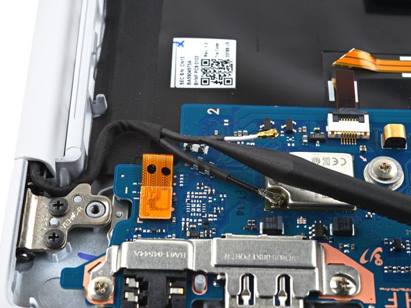
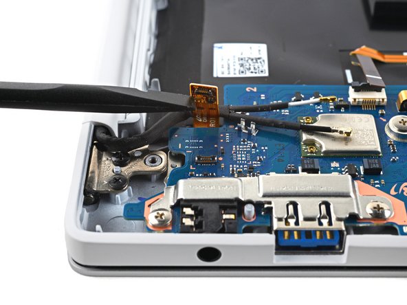
- Use a spudger to pry up and unclip the antenna cables from their slots on the daughterboard.
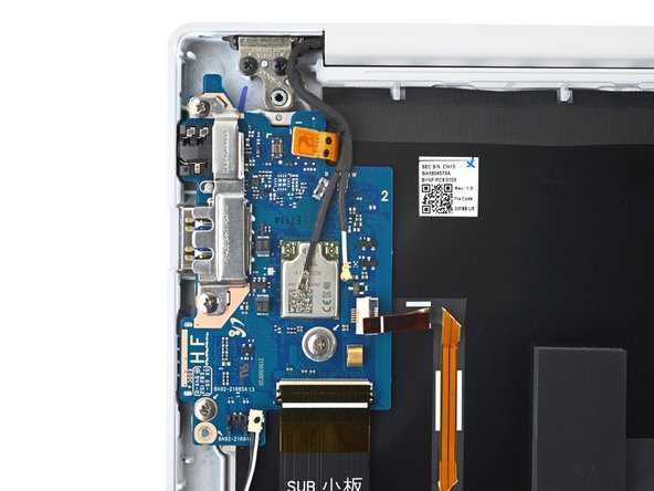
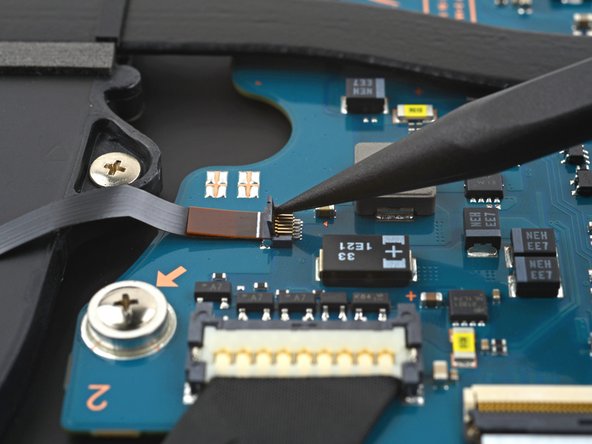
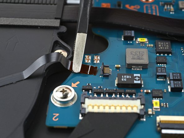
- Use the flat end of a spudger to pry up and disconnect the fingerprint sensor's press connector from the daughterboard.
- Use a Phillips screwdriver to remove the four 3.5 mm-long screws securing the daughterboard.
- Use tweezers, or your fingers, to remove the daughterboard port bracket.
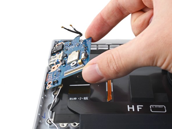
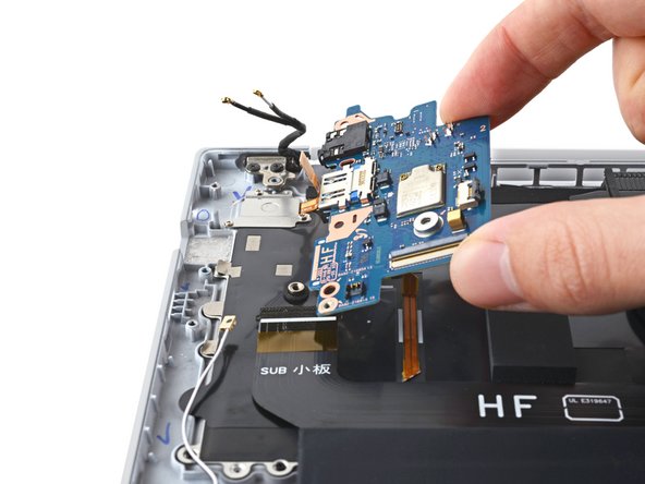
- Tilt the right edge of the daughterboard upward to separate it from its pegs in the frame.
- Pull the daughterboard toward the right edge of the laptop to separate the headphone jack and the HDMI port from their recesses in the frame.
- Remove the daughterboard.
- During reassembly, be sure to reinsert the daughterboard at a downward angle to position the headphone jack and the HMDI port back into their recesses.
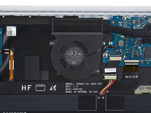
- Use a spudger to gently pry up the locking flap on the ZIF connector for the fan cable.
- Disconnect the fan cable by sliding it out from its socket on the motherboard.
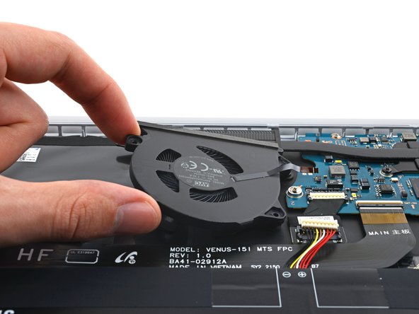
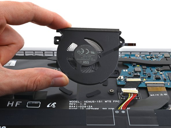
- Use a Phillips screwdriver to remove the three 3.5 mm-long screws securing the fan.
- The fan is lightly adhered to the frame.
- Lift the fan away from the frame to separate the adhesive.
- Remove the fan.
- Use a spudger to pry up and disconnect the bottom right speaker connector from the motherboard.
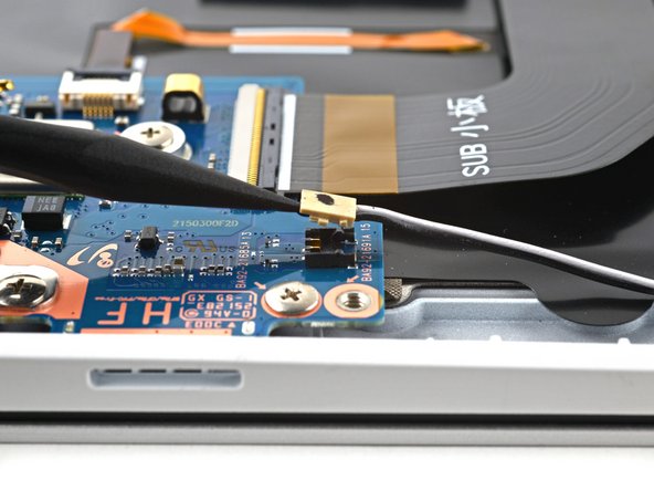
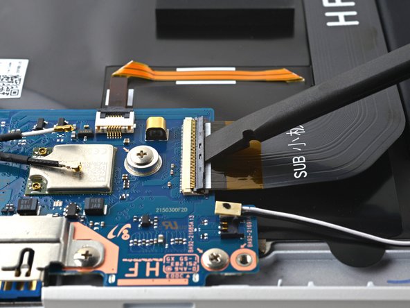
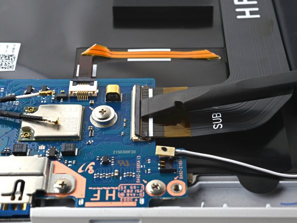
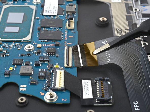
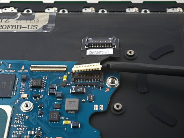
- Use a spudger to gently pry up the locking flap on the motherboard ZIF connector for the interconnect cable.
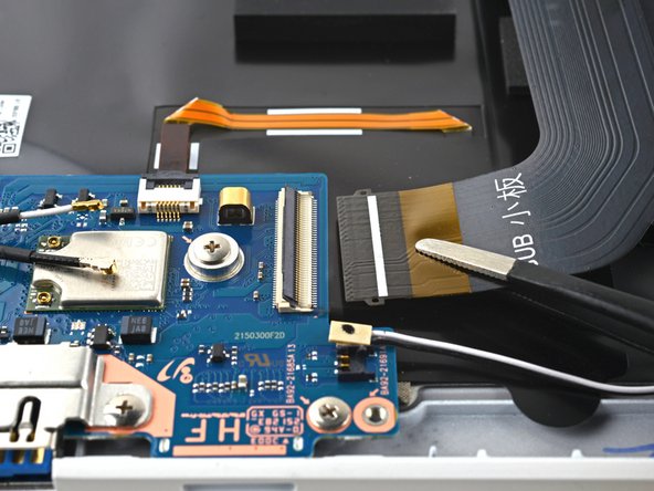
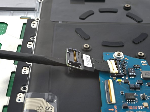
- Disconnect the interconnect cable by sliding it out from its socket on the motherboard.
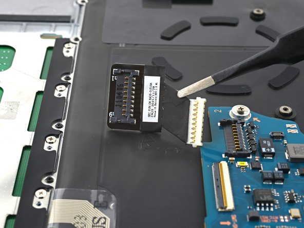
- Use your fingers, or tweezers, to remove the interconnect cable.
- Set the cable aside. You'll reuse it during reassembly.
- Insert a spudger between the frame and the bottom of the battery extender cable connector.
- Pry up and disconnect the battery extender cable connector.
- The battery extender is lightly adhered to the frame.
- Insert a spudger between the frame and the bottom of the battery extender.
- Pry up with the spudger to separate the adhesive.
- Remove the battery extender.
- During reassembly, reconnect the battery extender's connector to the motherboard before re-adhering it to the frame to ensure proper alignment.
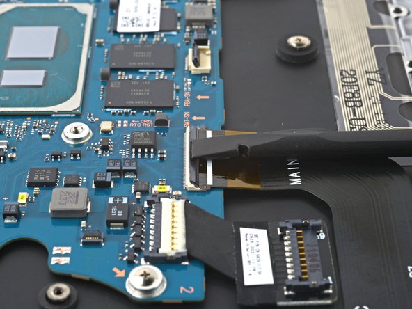
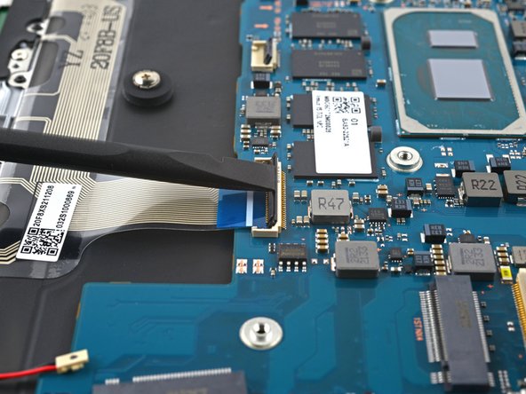
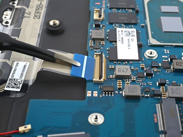
- Use a spudger to gently pry up the locking flap on the ZIF connector for the keyboard cable.
- Disconnect the keyboard cable by sliding it out from its socket on the motherboard.
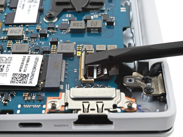
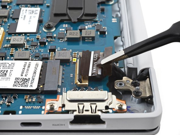
- Use a spudger to gently pry up the locking flap on the ZIF connector for the display cable.
- Disconnect the display cable by sliding it out from its socket on the motherboard.
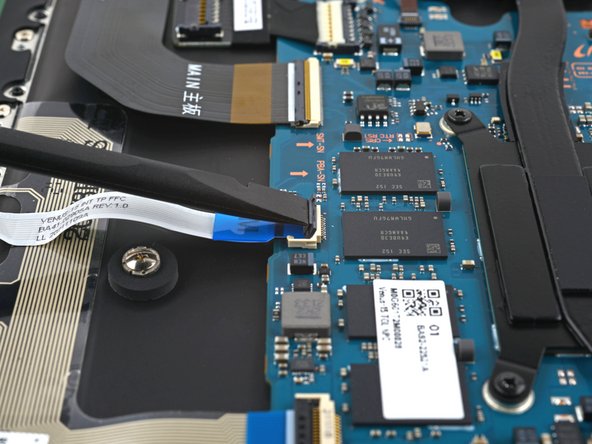
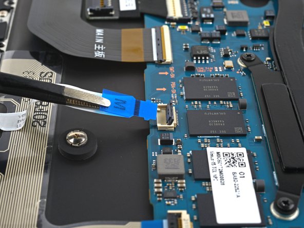
- Use a spudger to gently pry up the locking flap on the ZIF connector for the touchpad cable.
- Disconnect the touchpad cable by sliding it out from its socket on the motherboard.
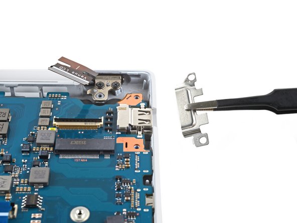
- Use a Phillips screwdriver to remove the two 3.5 mm-long screws securing the motherboard port bracket.
- Use tweezers, or your fingers, to remove the motherboard port bracket.
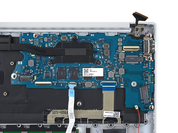
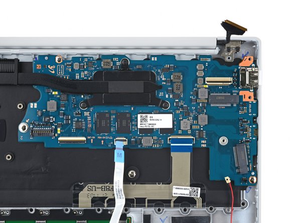
- Use a Phillips screwdriver to remove the three 3.5 mm-long screws securing the motherboard.
- If your laptop has a screw in the marked location, use a Phillips screwdriver to remove and transfer it to your replacement front case.
- This screw normally secures a secondary SSD drive.
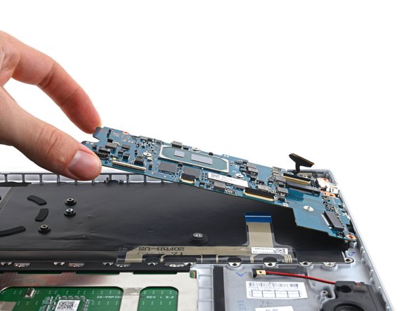
- Lift the left side of the motherboard upward to separate it from its pegs on the frame.
- Lift the motherboard straight up to separate the rest of the pegs.
- Remove the motherboard.
- During reassembly, make sure all of the connectors are above the motherboard before securing it back into the fame.
- Lift the bottom right speaker away from the frame to release it from its rubber grommets.
- Remove the bottom right speaker.
- Repeat the removal process for the bottom left speaker.
- Use a Phillips screwdriver to remove one 4.5 mm-long screw securing each screen hinge (two screws total).
- Each hinge has a second screw, which you should leave in place for now.
- Fully open the screen and stand your laptop up on one side.
- Use a Phillips screwdriver to remove the two remaining 4.5 mm-long screws (one from each hinge).
- Remove the topmost screw last, using one hand to steady both halves of the laptop to make sure they don't separate and fall over unexpectedly.
- Keep a firm grip on both the screen and frame of the laptop. Either half can fall unexpectedly during this step.
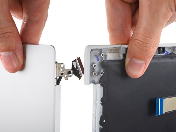
- Push both halves of the laptop together so that the hinges can be lifted clear of their recesses in the frame.
- Push the frame of the laptop away from you while pulling the screen toward you to separate it.
- Remove the screen.
- During reassembly, first install the hinge screws without tightening them fully. Then adjust the screen until it's correctly centered and aligned on each side. Finally, tighten the screws.
- You're now left with the front case.