Samsung Galaxy Book Pro 360 15" Front Case Replacement
ID: 154960
Description: Use this guide to replace the front case on...
Steps:
- Before you begin, shut down your laptop and unplug it.
- Close the screen and lay your laptop down with the rear case facing up to access the four rubber feet.
- Insert an opening pick between the rear case and the rubber foot.
- Pry up with the pick and dislodge the foot from the rear case.
- Use tweezers or your fingers to remove the rubber foot.
- Repeat this process on the remaining rubber feet.
- There are two types of rubber feet for this laptop. During reassembly, make sure the top feet say "M4" and the bottom feet say "M1".
- To reinstall a rubber foot, align it over the recess and push down until it's secured.
- Use a Phillips screwdriver to remove the four 4.5 mm screws securing the rear case.
- Throughout this repair, keep track of each screw and make sure it goes back exactly where it came from.
- Apply a suction handle to the middle of the rear case's bottom edge, as close to the edge as possible.
- Pull up on the handle with a strong, steady force to create a small gap between the rear case and the frame.
- This may take significant force and multiple tries.
- Insert an opening pick into the gap you created.
- Slide the opening pick along the bottom edge to release the clips securing the rear case.
- Continue sliding the pick along the perimeter of the laptop until all the clips securing the rear case have been released.
- Lift the rear case up and away from the laptop and remove it.
- During reassembly, this is a good point to power on your laptop and test all functions before sealing it up. Be sure to power your laptop back down before you continue working.
- Use tweezers or your fingers to peel up and remove the tape covering the battery connector.
- Set the tape aside. You'll reuse it during reassembly.
- Insert the flat end of a spudger under the battery cables, as close to the connector as possible.
- Gently pry up and disconnect the battery connector from its socket.
- Use a Phillips screwdriver to remove the four 4.5 mm screws securing the battery.
- Take care not to puncture the battery with your screwdriver—a punctured battery may leak dangerous chemicals or cause a fire.
- Lift the battery straight out of its recess and remove it.
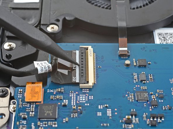
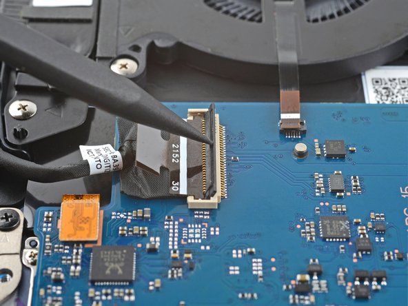
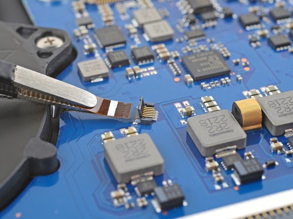
- Use the pointed end up a spudger to pry up the locking flap on the left fan cable's ZIF connector.
- During reassembly, make sure that all seven cables are connected to the daughterboard.
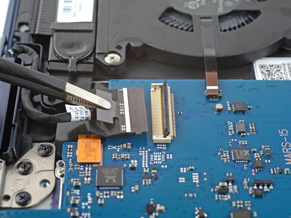
- Grip the left fan cable's pull tab with tweezers and gently pull the cable out of its socket.
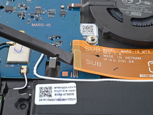
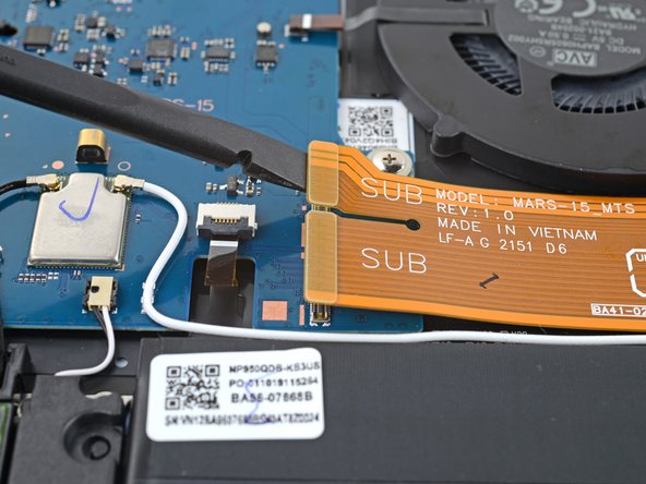
- Use the flat end of spudger to pry up and disconnect both of the interconnect cable's press connectors from the daughterboard.
- To re-attach press connectors like these, carefully align and press down on one side until it clicks into place, then repeat on the other side. Don't press down on the middle. If the connector is misaligned, the pins can bend and cause permanent damage.
- Use the pointed end of a spudger to pry up and disconnect the bottom left speaker's connector from the daughterboard.
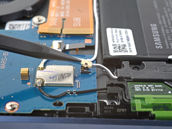
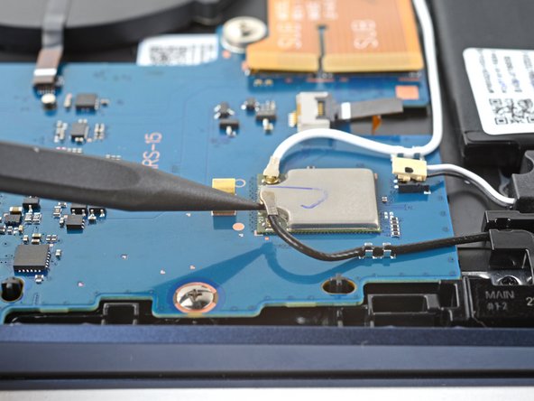
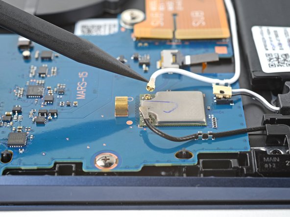
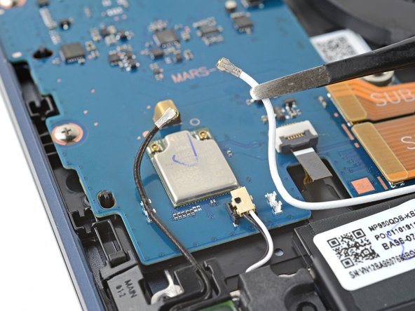
- Insert the pointed end of a spudger under the black antenna cable and slide it as close to the connector as possible.
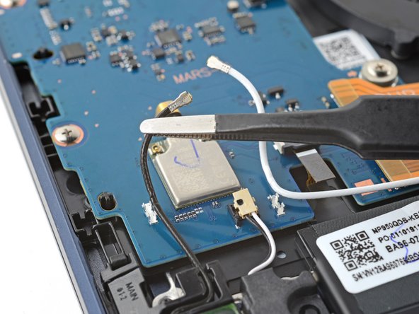
- Gently lift straight up to disconnect the antenna.
- The connector is very delicate and can easily break if a quick or strong force is applied.
- Repeat the disconnection procedure on the white antenna cable.
- To reattach coaxial connectors like these, align the connector over its socket and press down with the flat end of a spudger. The connector should snap into place. This can be tricky and may take a few tries.
- Use tweezers or your fingers to lift the black and white antenna cables out of their clips on the daughterboard.
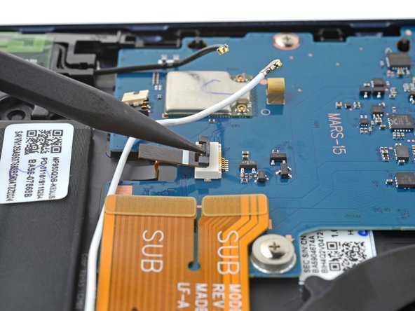
- Use the pointed end of a spudger to pry up the locking flap on the backlight cable's connector.
- Grip the backlight cable's pull tab with tweezers and gently pull the cable out of its socket.
- Use a spudger to pry up the locking flap on the left display cable's ZIF connector.
- Grip the left display cable's pull tab with tweezers or your fingers and gently pull the cable out of its socket.
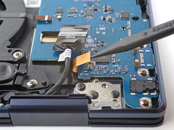
- Use the pointed end of a spudger to pry up and disconnect the fingerprint sensor's press connector.
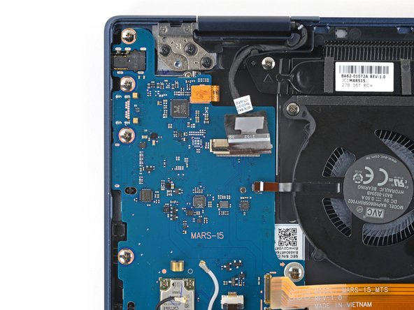
- Use a Phillips screwdriver to remove the five 3.5 mm screws securing the daughterboard.
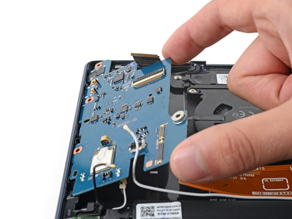
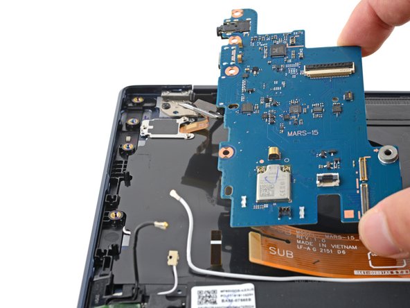
- Lift the right side of the daughterboard up and pull towards the center of the laptop to remove it.
- During reassembly:
- Move all cables that connect to the daughterboard (display, fingerprint, interconnect, speaker, backlight, and antennas) out of the way so they don't get stuck under the daughterboard when it's reinserted.
- Reinsert the daughterboard at a downward angle to position the headphone jack, USB-C port, and memory slot back into their recesses.
- Before securing the daughterboard, make sure the alignment pins on the frame are in their cutouts on the daughterboard.
- Use a Phillips #00 screwdriver to remove the three 2.5 mm screws securing the fingerprint sensor bracket on the top left corner of the laptop.
- Use tweezers or your fingers to remove the fingerprint sensor bracket.
- Use tweezers or your fingers to remove the fingerprint sensor.
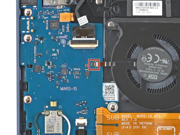
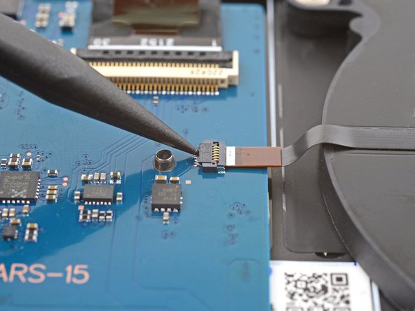
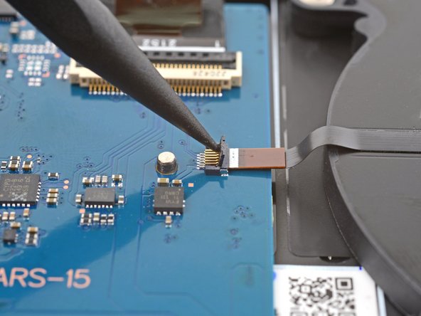
- Use the pointed end of a spudger to pry up the locking flap on the right fan cable's ZIF connector.
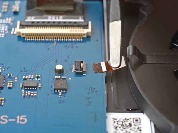
- Grip the right fan cable's pull tab with tweezers and gently pull the cable out of its socket.
- Remove the six 3.5 mm screws securing the fans.
- Lift both fans straight up and remove them.
- Use the pointed end of a spudger to pry up and disconnect the bottom right speaker's connector from the motherboard.
- During reassembly, make sure you've connected these five cables to the motherboard.
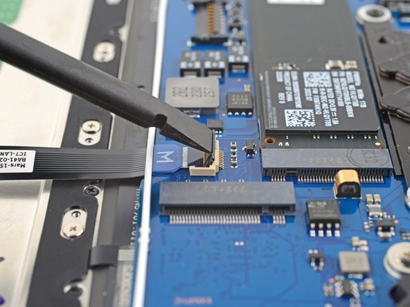
- Use the flat end of a spudger to pry up the locking flap on the keyboard cable's ZIF connector.
- Grip the keyboard cable's pull tab with tweezers or your fingers and gently pull the cable out of its socket.
- Use the flat end of a spudger to pry up the locking flap on the touchpad's ZIF connector on the motherboard.
- Grip the touchpad cable's pull tab with tweezers and gently pull the cable out of its socket on the motherboard.
- Use your fingers or a spudger to peel up the tape covering the ZIF connector on the touchpad.
- Remove the tape.
- Set the tape aside. You'll reuse it during reassembly.
- Use the pointed end up a spudger to pry up the locking flap on the ZIF connector.
- Grip the touchpad cable's pull tab with tweezers and gently pull the cable out of its socket on the touchpad.
- Remove the touchpad cable.
- Set the cable aside. You'll reuse it during reassembly.
- Use the flat end of spudger to pry up the locking flap on the right display cable's ZIF connector.
- Grip the right display cable's pull tab with tweezers or your fingers and gently pull the cable out of its socket.
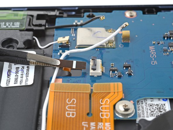
- Gently pull the white antenna cable out of the three clips securing it to the motherboard.
- Use the flat end of a spudger to pry up and disconnect both of the interconnect cable's press connectors from the motherboard.
- Remove the interconnect cable.
- Set the cable aside. You'll reuse it during reassembly.
- Slowly pull the right display cable out of its recess.
- A small clip secures the cable.
- Repeat the process on the left display cable.
- During reassembly, make sure the display cables are secured under their clips.
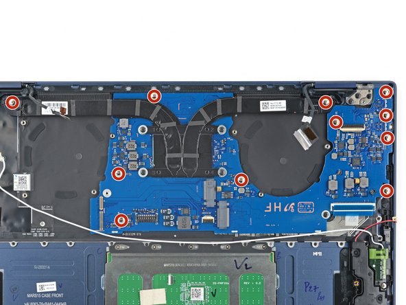
- Use a Phillips screwdriver to remove the 11 3.5 mm screws securing the motherboard.
- Lift the motherboard straight up and remove it.
- Before securing the motherboard during reassembly:
- Move all cables that connect to the motherboard (display, keyboard, speaker, and antenna) out of the way so they don't get stuck under the motherboard when it's reinserted.
- Make sure the alignment pins on the frame are in their cutouts on the motherboard.
- Push down on right edge of the motherboard to ensure the USB-C and thunderbolt ports are in their recesses.
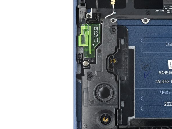
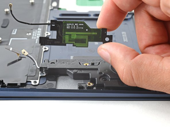
- Use a Phillips screwdriver to remove the 3.5 mm screw securing the right antenna.
- Use a Phillips screwdriver to remove the 3.5 mm screw securing the left antenna.
- Insert a pick between the left antenna and the bottom left speaker.
- Pry up with the pick to dislodge the antenna.
- Remove the antenna from its recess.
- During reassembly, make sure to insert the top of the antennas under their brackets before laying them in their recesses.
- Repeat the removal procedure on the right antenna.
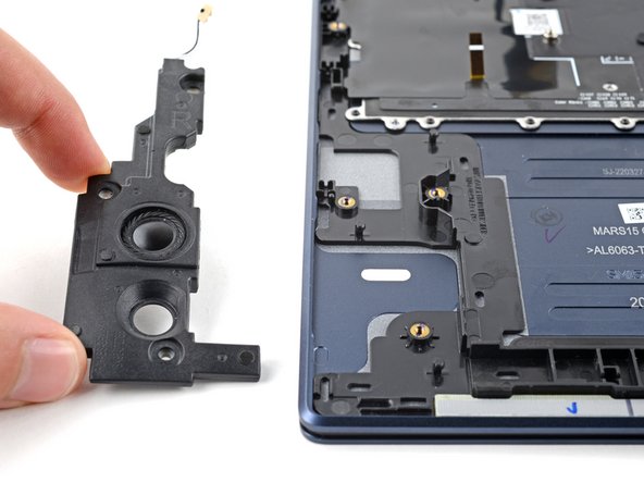
- Insert an opening pick between the bottom left speaker's left edge and the frame.
- Pry up with the opening pick to dislodge the speaker from its recess.
- Remove the speaker.
- Repeat the removal process on the bottom right speaker.
- Open the laptop until it's completely flat and lay it down with the display and keyboard facing down.
- Before laying the laptop down, make sure you have a clean surface that is clear of items that could damage the display.
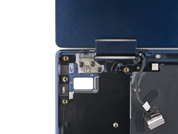
- Use a Phillips screwdriver to remove the three 3.5 mm screws securing the left screen hinge.
- During reassembly, install the screws from right to left.
- Use a Phillips screwdriver to remove the three 3.5 mm screws securing the right screen hinge.
- During reassembly, install the screws from left to right.
- Lift the screen away from the laptop and remove it.
- You're left with the front case.