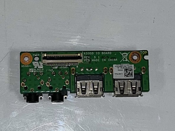
Asus A53S I/O Board Replacement
ID: 155110
Description: This guide will show you how to replace a I/O...
Steps:
- Power off your device and remove the battery before beginning this guide.
- Flip the laptop so the underside is facing up.
- Using a Phillips #01 screwdriver, unscrew the two 6 mm screws.
- Remove the back plate.
- Separate your screws by step for easier assembly.
- Place the spudger under the white wire and pull it up gently, disconnecting it from the wifi card.
- Use the same method on the black wire.
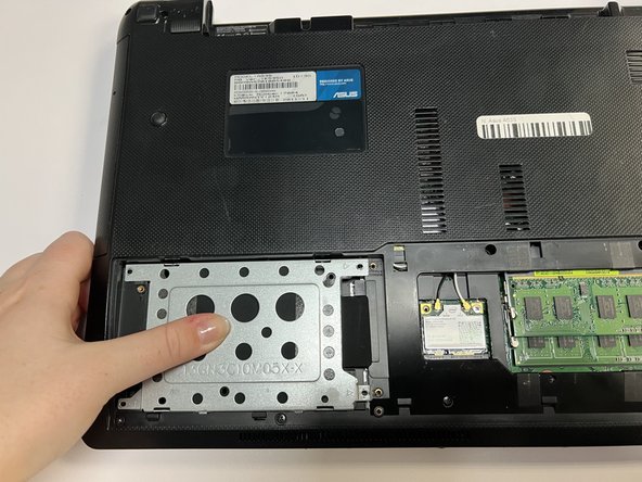
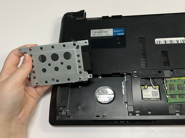
- Push the hard drive to the left and remove it.
- Using a Phillips #01 screwdriver, unscrew the fifteen 6 mm screws at the indicated places.
- Flip over the laptop and open it.
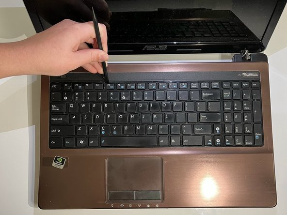
- Using the spudger, insert the flat end into the notches at the top of the keyboard and slowly slide and "pop" the keyboard up and out of the device.
- Using the flat end of the spudger, lift the black ZIF connector lock bar and disconnect the keyboard from the computer.
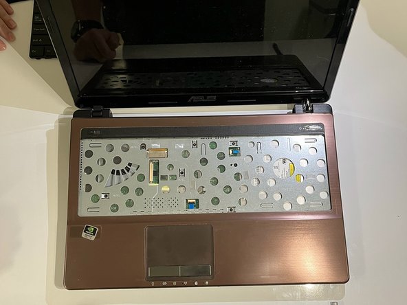
- Remove the keyboard.
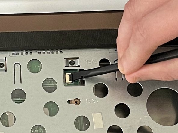
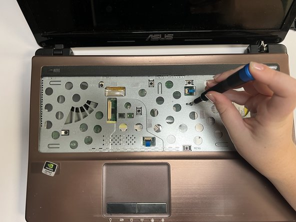
- Using the spudger, place the flat end under the ZIF connector lock bar holding the power switch. Push the spudger up and to the left, disconnecting the power switch.
- Use the same technique on the touchpad to disconnect it.
- Using a Phillips #01 screwdriver, unscrew the seven 6 mm screws at the indicated places.
- Gently pull out the optical drive.
- Flip the laptop back over so that the bottom is facing up.
- Use a Phillips #01 screwdriver to unscrew the three 6 mm screws at the indicated places.
- Turn the laptop back over so that you can open it.
- Gently separate the cover from the laptop by putting an iFixit Opening Tool between the cover and the lower part of the laptop and levering them apart.
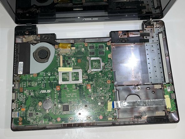
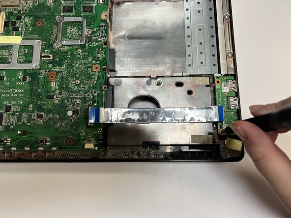
- Remove the yellow tape.
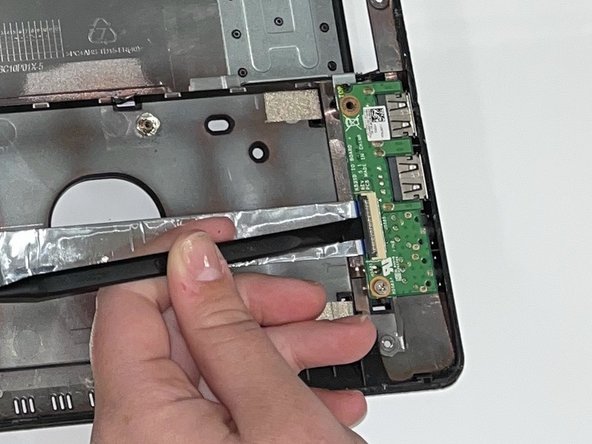
- Using the flat end of a spudger, flip up the ZIF connector lock bar, disconnecting the USB board from the mother board.
- Repeat this technique on the other side of the USB connector.
- Using a Phillips #01 screwdriver, unscrew the 5 mm screw at the indicated place.
- Gently remove the USB board.