Samsung Galaxy S22 Ultra 5G mmWave Antennas and Interconnect Cables Replacement
ID: 155120
Description: This is a prerequisite-only guide! This guide...
Steps:
- Let your phone's battery drain to below 25% before starting this repair. A charged lithium-ion battery may catch fire if damaged.
- Heat an iOpener and apply it to the right edge of the back cover for two minutes.
- A hair dryer, heat gun, or hot plate may also be used, but be careful not to overheat the phone—the display and internal battery are susceptible to heat damage.
- While you wait for the adhesive to soften, note the following:
- There's adhesive securing the back cover around the perimeter of the frame.
- The adhesive is strongest in the bottom right and top left corners.
- Apply a suction handle to the back cover, as close to the center of the right edge as possible.
- Pull up on the suction handle with strong, steady force to create a gap between the cover and the frame.
- If you have trouble creating a gap, apply more heat to further soften the adhesive. Follow the iOpener instructions to avoid overheating.
- Insert an opening pick into the gap.
- Slide the pick back and forth along the right edge to slice through the adhesive.
- Leave the pick inserted near the bottom of the right edge to prevent the adhesive from resealing.
- Apply a heated iOpener to the bottom edge of the back cover for two minutes.
- Insert a second opening pick at the bottom right corner.
- Angle the pick upward to match the curved edge and rotate it around the bottom right corner.
- Be careful while slicing around the corners, as the glass is very fragile here. Work slowly to avoid cracking the glass.
- Slide your opening pick to the bottom left corner to slice the adhesive.
- Leave the pick in the bottom left corner to prevent the adhesive from resealing.
- Apply a heated iOpener to the left edge of the back cover for two minutes.
- Insert a third opening pick at the bottom left corner.
- Angle the pick upward to match the curved edge and rotate it around the bottom left corner.
- Be careful while slicing around the corners, as the glass is very fragile here. Work slowly to avoid cracking the glass.
- Slide your opening pick along the left edge to slice the adhesive, stopping when you reach the power button.
- Only insert the pick up to 5 mm, as you may damage the antenna flex cable or the power button cable.
- Leave the pick in the left edge to prevent the adhesive from resealing.
- Heat an iOpener and apply it to the top edge of the back cover for two minutes.
- Insert an opening pick in the gap at the top right edge.
- Angle the pick upward to match the curved edge and rotate it around the top right corner.
- Be careful while slicing around the corners, as the glass is very fragile here. Work slowly to avoid cracking the glass.
- Slide the pick to the top left corner to slice the adhesive.
- Only insert the pick up to 4 mm, as you may damage the cameras or sensors.
- Leave the pick in to prevent the adhesive from resealing.
- Only insert the pick up to 4 mm, as you may damage the cameras.
- Insert an opening pick in the gap at the top left edge.
- Angle the pick upward to match the curved edge and rotate it around the top left corner.
- Only insert the pick up to 4 mm, as you may damage the cameras.
- Slide the pick toward the bottom camera to slice through the remaining adhesive, stopping before you reach the power button.
- Grab and remove the back cover.
- If your cover is still sticking to the frame, slide an opening pick around the perimeter until the cover completely separates.
- During reassembly:
- This is a good point to power on your phone and test all functions before sealing it up. Be sure to power your phone back down completely before you continue working.
- Remove any adhesive chunks with a pair of tweezers or your fingers. Apply heat if you're having trouble separating the adhesive.
- If you're using custom-cut adhesives, follow this guide.
- If you're using double-sided tape, follow this guide.
- The wireless charging coil is lightly adhered to the battery.
- Be careful not to strain or tear the display interconnect cable under the right side of the charging coil.
- Insert an opening pick between the right edge of the wireless charging coil and the battery.
- Slide the pick along the right edge to separate the adhesive.
- Use the pointed end of a spudger to pry and disconnect the NFC antenna press connector from the motherboard.
- Repeat for the wireless charging coil press connector.
- To re-attach press connectors, carefully align and press down on one side until it clicks into place, then repeat on the other side. Don't press down on the middle. If the connector is misaligned, the pins can bend and cause permanent damage.
- Use your Phillips screwdriver to remove the five 3.5 mm-long screws securing the NFC antenna and charging coil.
- Use your Phillips screwdriver to remove the six 3.5 mm screws securing the loudspeaker.
- Insert the pointed end of your spudger between the upper right corner of the loudspeaker and the frame.
- Pry up to unclip the loudspeaker from the frame.
- Don't pry against the battery. Use protrusions in the frame for leverage.
- During reassembly, press around the perimeter of the loudspeaker to clip it to the frame.
- Grab and remove the NFC, wireless charging coil, and loudspeaker from the frame.
- The wireless charging coil holds these parts together.
- Use the pointed end of your spudger to pry up and disconnect the battery press connector.
- Use the pointed end of your spudger to pry up and disconnect the lower 5G mmWave antenna press connector.
- Use your Phillips screwdriver to remove the two 3.5 mm-long screws securing the antenna bracket.
- Insert the pointed end of your spudger between the lower screw mount of the antenna bracket and the frame.
- Pry up on the bracket until you can grab it with blunt nose tweezers or your fingers.
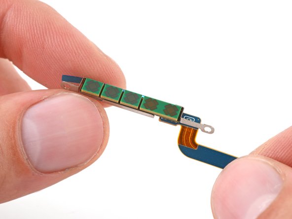
- Remove the lower 5G mmWave antenna.
- Before reinstalling the lower 5G mmWave antenna, replace the bracket with a new one. If you don't have a new bracket, skip this step.
- Remove the antenna and connector from the old bracket.
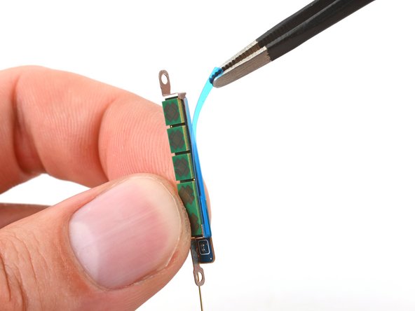
- Remove the L-shaped adhesive liner from your new bracket.
- Place the antenna in the bracket's recess with the connector fed underneath the longer screw mount.
- Remove the thin adhesive liner on the outside of the bracket before installing it in the frame.
- Use the pointed end of your spudger to pry up and disconnect the upper 5G mmWave antenna press connector.
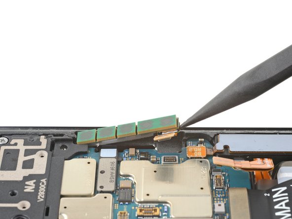
- Insert the pointed end of your spudger in the gap between the bottom edge of the 5G mmWave antenna and the motherboard.
- Pry the antenna out of its recess until you can grab it with your fingers or blunt nose tweezers.
- If the antenna feels stuck, apply a heated iOpener for two minutes to soften the adhesive.
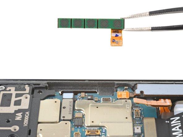
- Remove the upper 5G mmWave antenna.
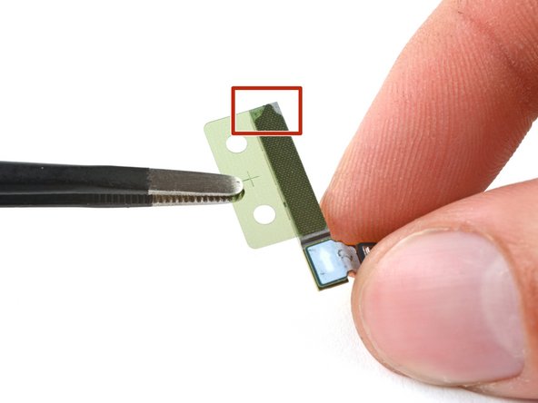
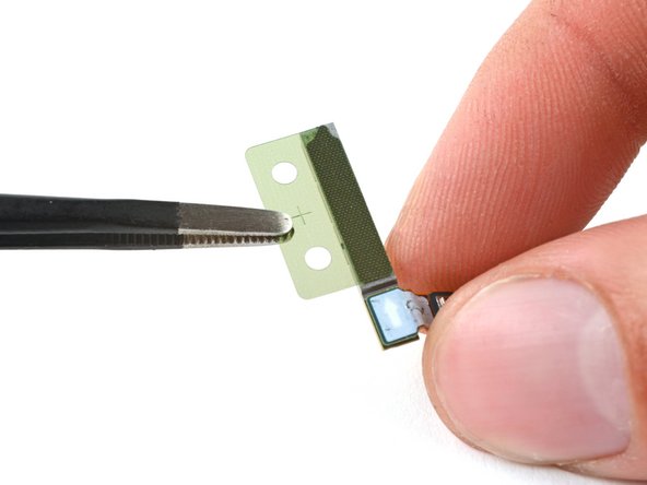
- Replace the adhesive on the upper 5G mmWave antenna before reinstalling it. If you don't have replacement adhesive, reuse your old one or use custom-cut adhesive.
- Remove the existing adhesive from the antenna with blunt nose tweezers or your fingers.
- Remove the clear liner from your new adhesive.
- Apply the new adhesive to the bottom of the antenna, with its round end farthest from the connector.
- Remove the green liner from the adhesive before reinstalling the antenna in the frame.
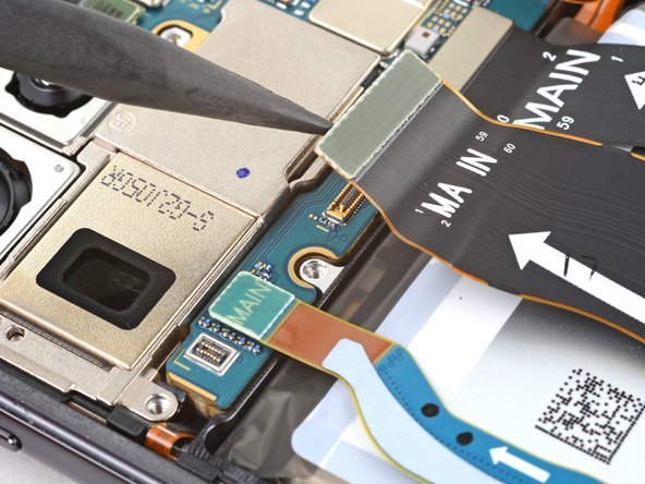
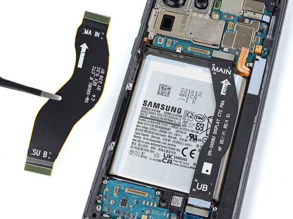
- Use the pointed end of your spudger to pry up and disconnect the primary interconnect cable from the motherboard.
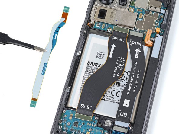
- Repeat for the secondary interconnect located to the left of the primary cable.
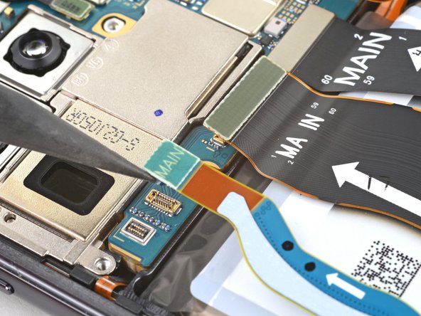
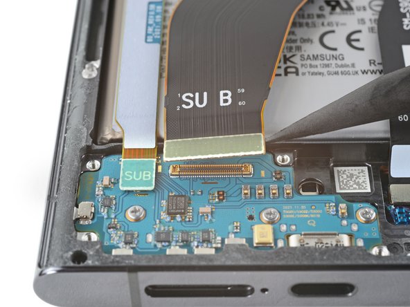
- Use the pointed end of your spudger to pry up and disconnect the primary interconnect cable from the charging board.
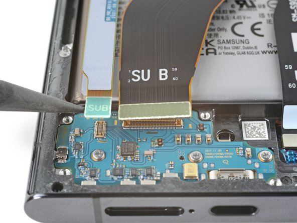
- Repeat for the secondary interconnect cable.
- Grab and remove the interconnect cables from the frame.