Bissell PowerFresh Steam Mop Power Cord Replacement
ID: 155211
Description: If the power cord of your Bissell PowerFresh...
Steps:
- Turn the unit on its front so the bottom is facing up.
- Remove the eight screws using a Phillips #2 screwdriver.
- Remove the single screw holding the handle in place using a Phillips #2 screwdriver.
- Pull the handle out.
- Remove the two screws from the underside of the mop where the mop head is connected using a Phillips #2 screwdriver.
- Remove the mop head connector.
- Remove two screws using a Phillips #2 screwdriver.
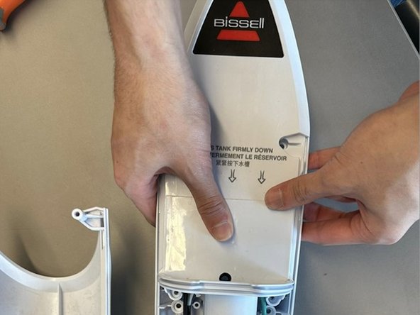
- Pull the bottom portion of the front housing away from the rest of the mop.
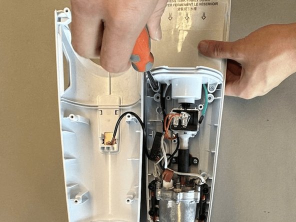
- Remove two screws that are inside the unit using a Phillips #2 screwdriver.
- Pull the top housing upwards to detach it from the water pump.
- The main components pictured are the control circuit, the water pump and the heating unit.
- Remove the two screws from the plastic clamp using a Phillips #2 screwdriver.
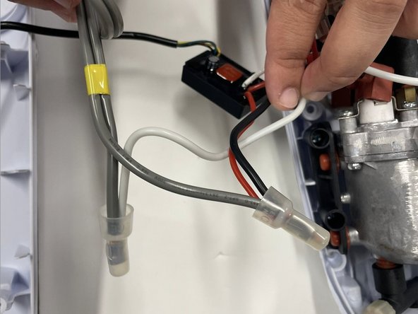
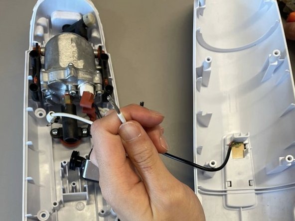
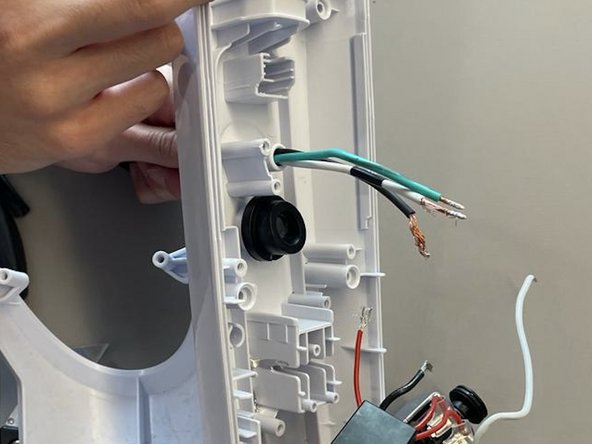
- Using a flush cutter or pliers, cut the original power cable and the white, black, and red wires as close to the plastic protective caps as possible.
- Be careful not to disconnect the wires from the control circuit.
- The damaged power cable can now be removed by pulling through from the back of the unit.
- Plug in the soldering iron and allow it to heat up to approximately 350°C. For more soldering instructions, check out the How To Solder and Desolder Connections guide.
- Prep the replacement cable and wires by using a wire stripper or pliers to remove approximately 0.5 inches of the plastic insulation.
- Strip the hot and neutral wires belonging to the unit. In this model, the hot wires are black and red and the neutral wire is white.
- Strip the wires belonging to the replacement cable.
- Feed the replacement cable through the entry point at the back of the unit. If it does not fit, the rubber insulation can be stripped further using a utility knife.
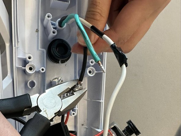
- Solder the neutral wire from the replacement cable to the white wire of the unit.
- It may be helpful to have a second pair of hands to hold the wires steady while soldering.
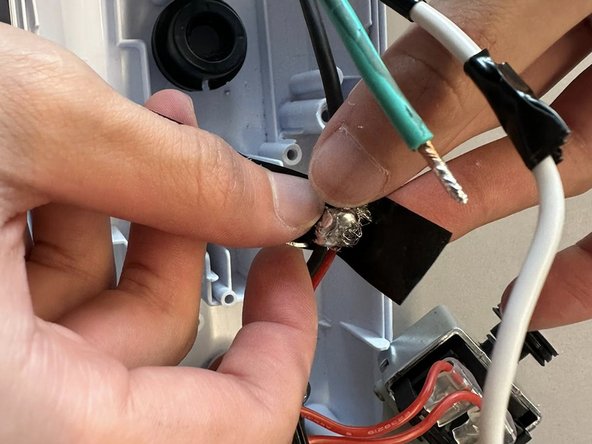
- Solder the hot wire from the replacement cable to the black and red wires of the unit.
- Pliers can be used to crimp solder around the wires in case it becomes loose.
- Tape around soldered wires with electrical tape.
- The power cable for this model does not utilize the ground wire (green). If the replacement cable contains a ground wire, tape around the exposed wire using electrical tape.
- Shrink tubing can also be used to provide seamless reconnection and protection of the wires.
- Secure modules of the unit back into the housing.