Samsung Galaxy S22 Plus Screen and Battery Assembly Replacement
ID: 155215
Description: Follow this guide to replace the screen and...
Steps:
- Insert a SIM eject tool, bit, or straightened paper clip into the SIM card tray hole on the bottom edge of the phone.
- Press the SIM eject tool into the SIM card tray hole to eject the SIM card tray.
- Remove the SIM card tray.
- If you accidentally inserted the SIM eject tool into a microphone hole, don't worry! You most likely didn't damage the microphone.
- Let your phone's battery to drain below 25% before starting this repair. A charged lithium-ion battery may catch fire if damaged.
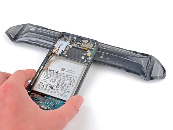
- Prepare an iOpener and apply it to the bottom edge of the back cover for three minutes to loosen the adhesive underneath.
- A hair dryer, heat gun, or hot plate may also be used, but be careful not to overheat the phone—the display and internal battery are both susceptible to heat damage.
- Secure a suction handle to the bottom edge of the back cover, as close to the edge as possible.
- If the back cover is cracked, the suction handle may not stick. Try lifting it with strong tape, or superglue the suction handle in place and allow it to dry so you can proceed.
- Lift the back cover with the suction handle to create a small gap between the back cover and the frame.
- If you have trouble creating a gap, apply more heat to further soften the adhesive. Follow the iOpener instructions to avoid overheating.
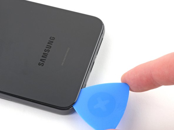
- Insert an opening pick into the gap you created.
- Remove the suction handle.
- Slide the opening pick along the bottom edge to slice the adhesive.
- If the adhesive becomes hard to cut, it has most likely cooled down. Use your iOpener for two to three minutes to reheat it.
- Leave the opening pick inserted near the bottom left corner to prevent the adhesive from resealing.
- Apply the heated iOpener to the left edge of the phone for 3 minutes to soften the adhesive.
- Reheat your iOpener for 30 seconds if necessary.
- Be careful not to overheat the iOpener. Overheating may cause the iOpener to burst.
- A properly heated iOpener should stay warm for up to 10 minutes.
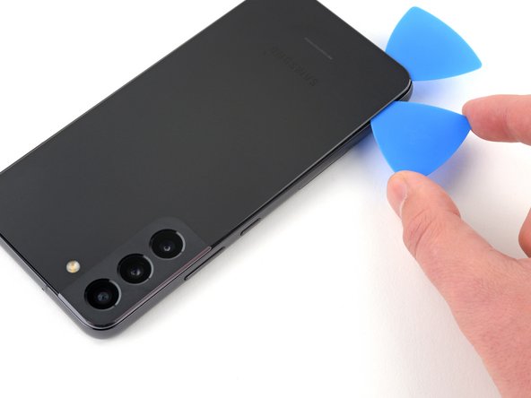
- Insert a second opening pick into the gap created near the bottom left corner.
- Don't insert the opening pick more than 5 mm, or you risk damaging cables near the camera module.
- Slide the opening pick along the left edge to slice the adhesive.
- Leave the opening pick inserted near the top left corner to prevent the adhesive from resealing.
- Apply your heated iOpener to the right edge of the phone for 3 minutes to soften the adhesive.
- Reheat your iOpener for 30 seconds if necessary.
- Be careful not to overheat the iOpener. Overheating may cause the iOpener to burst.
- A properly heated iOpener should stay warm for up to 10 minutes.
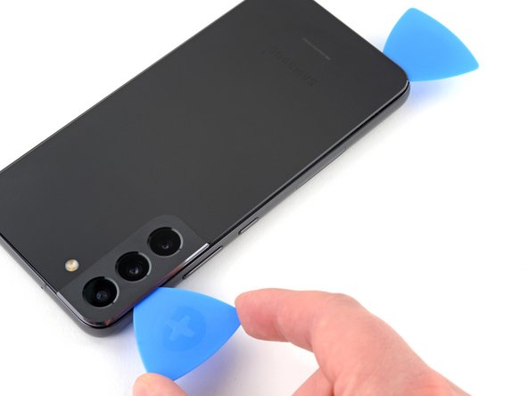
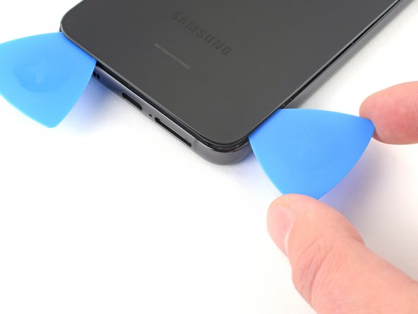
- Insert a third opening pick into the gap created along the bottom edge.
- Slide the opening pick around the bottom right corner of the back cover to slice the adhesive.
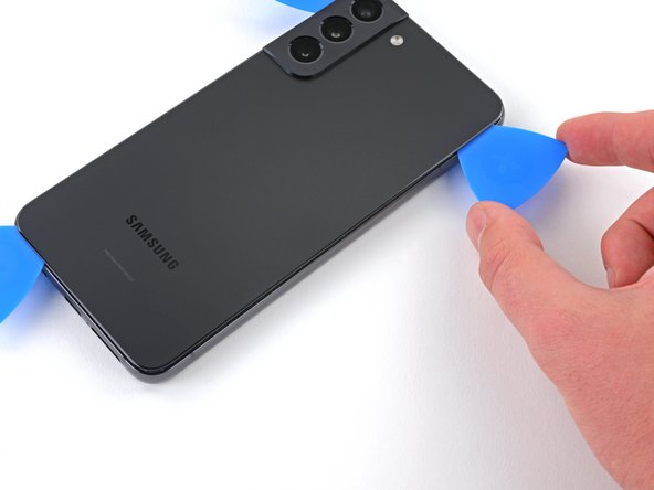
- Continue sliding the opening pick up along the right edge of the back cover to slice the adhesive.
- Don't insert the opening pick more than 5 mm to avoid damaging any internal components.
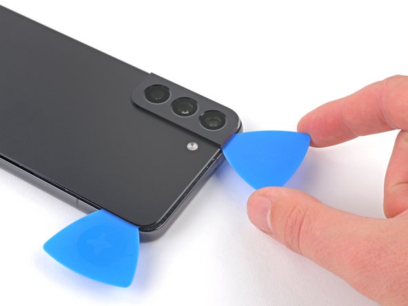
- Leave the opening pick inserted near the top right corner to prevent the adhesive from resealing.
- Apply your heated iOpener to the top edge of the phone for 3 minutes to soften the adhesive.
- Reheat your iOpener for 30 seconds if necessary.
- Be careful not to overheat the iOpener. Overheating may cause the iOpener to burst.
- A properly heated iOpener should stay warm for up to 10 minutes.
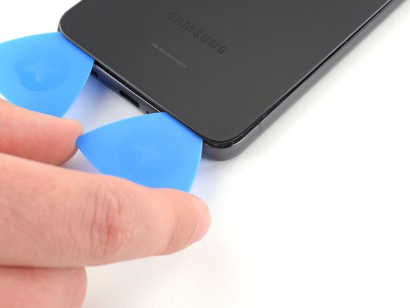
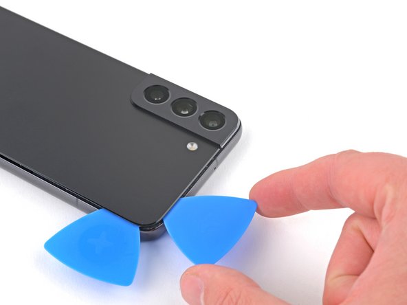
- Slide the opening pick in the top left corner across the top edge to separate the remaining adhesive.
- Don't insert the pick more than 5 mm to avoid damaging or smearing the rear cameras and flash.
- Remove the back cover.
- During reassembly:
- This is a good point to power on your phone and test all functions before sealing it up. Be sure to power your phone back down completely before you continue working.
- Remove any adhesive chunks with a pair of tweezers or your fingers. Apply heat if you're having trouble separating the adhesive.
- If you're using custom-cut adhesives, follow this guide.
- If you're using double-sided tape, follow this guide.
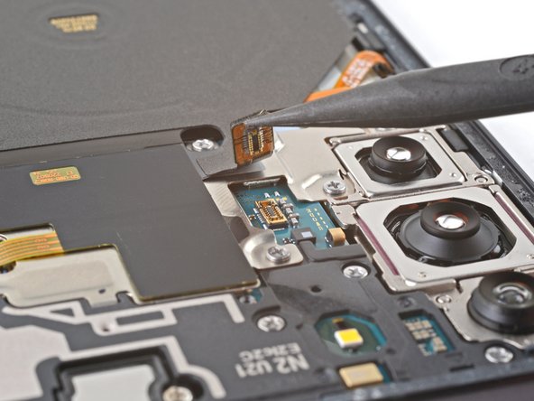
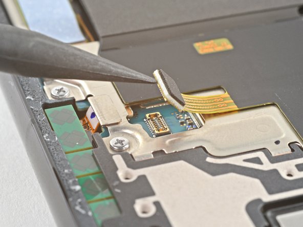
- Use the pointed end of your spudger to pry up and disconnect the charging coil's press connector from the motherboard.
- Use the pointed end of your spudger to pry up and disconnect the NFC antenna cable from the motherboard.
- Use your Phillips screwdriver to remove the six 3.5 mm screws securing the charging coil.
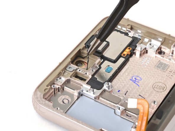
- Use your Phillips screwdriver to remove the seven 3.5 mm screws securing the loudspeaker.
- Insert your spudger in between the left edge of the loudspeaker and the frame.
- Pry up to disconnect the clips securing the loudspeaker.
- Be careful to not separate the loudspeaker from the charging coil.
- During reassembly, press the loudspeaker into the frame until the clips engage.
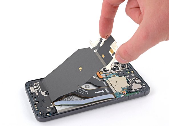
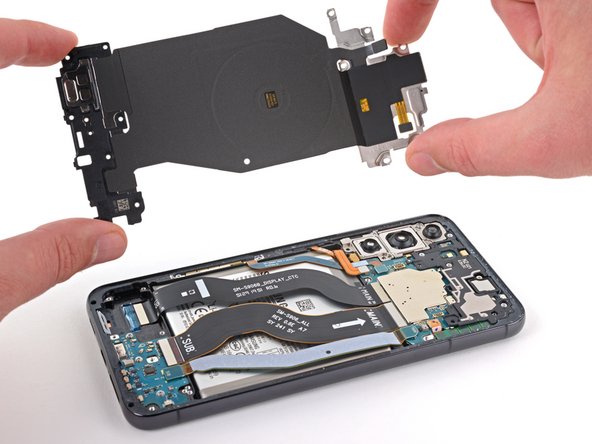
- Gently remove the charging coil & NFC antenna assembly.
- Do not separate the charging coil from the loudspeaker.
- Use your spudger to pry up and disconnect the battery's press connector.
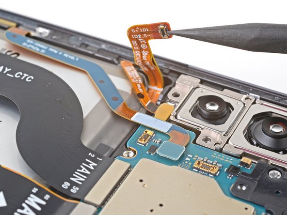
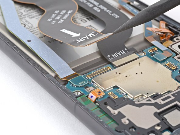
- Use your spudger to pry up and disconnect the primary interconnect cable from the motherboard.
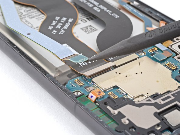
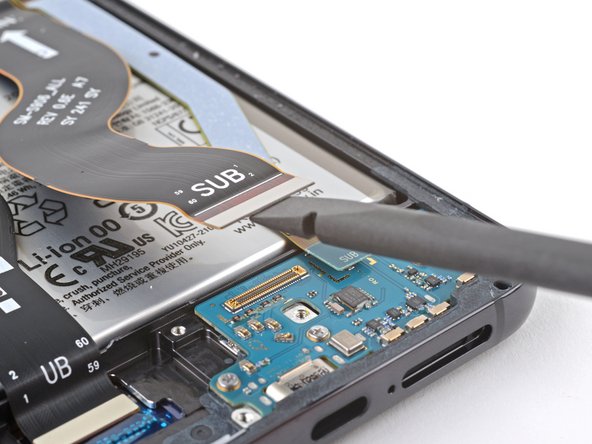
- Use your spudger to pry up and disconnect the secondary interconnect cable from the motherboard.
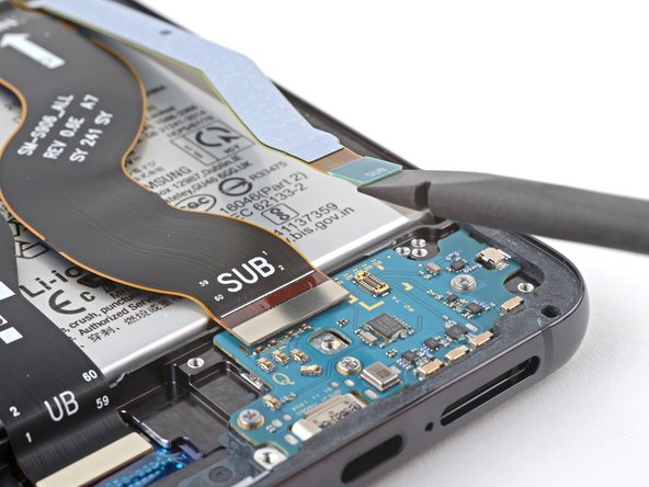
- Use your spudger to pry up and disconnect the primary interconnect cable from the charging board.
- Use your spudger to pry up and disconnect the secondary interconnect cable from the charging board.
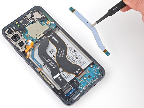
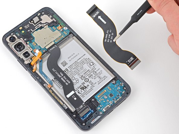
- Use tweezers, or your fingers, to remove the interconnect cables.
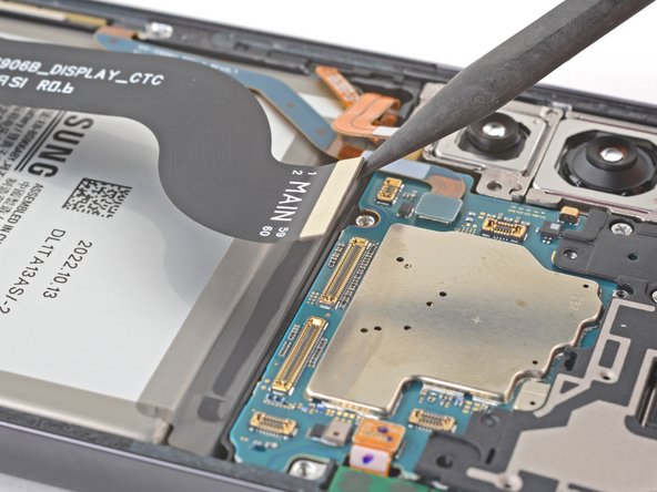
- During reassembly, make sure that the end of each cable labeled MAIN is connected to the motherboard, and the ends labeled SUB are connected to the charging board.
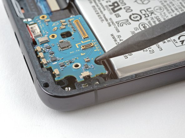
- Use your Phillips screwdriver to remove the three 3.4 mm screws securing the charging board.
- Insert the pointed end of a spudger between the top right edge of the charging board and the frame.
- Pry up to lift the charging board enough to reach it with your fingers.
- Pull the charging board towards the top of the phone at a 30-degree angle and remove it.
- During reinstallation, make sure the red gasket around the charging port is seated flush against the edge of the phone to retain as much ingress protection as possible.
- Use your spudger to pry up and disconnect the display cable from the motherboard.
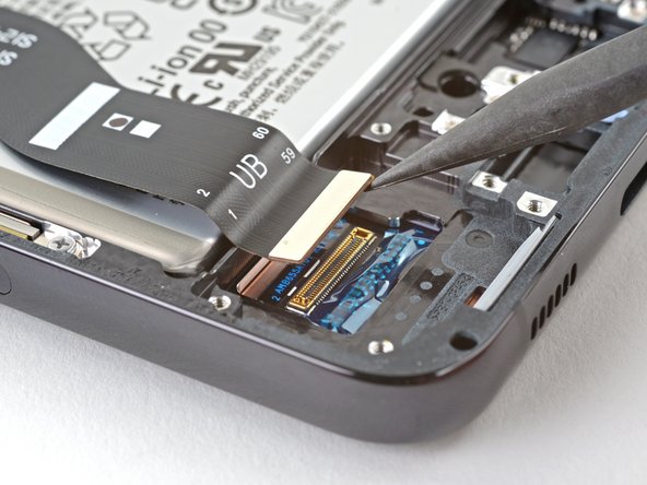
- Use your spudger to pry up and disconnect the display cable from its press connector below the battery.
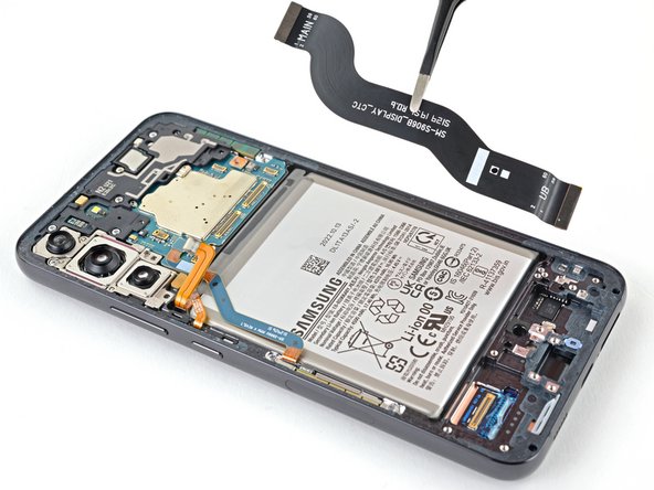
- Remove the display cable.
- Set the cable aside. You'll reuse it during reassembly.
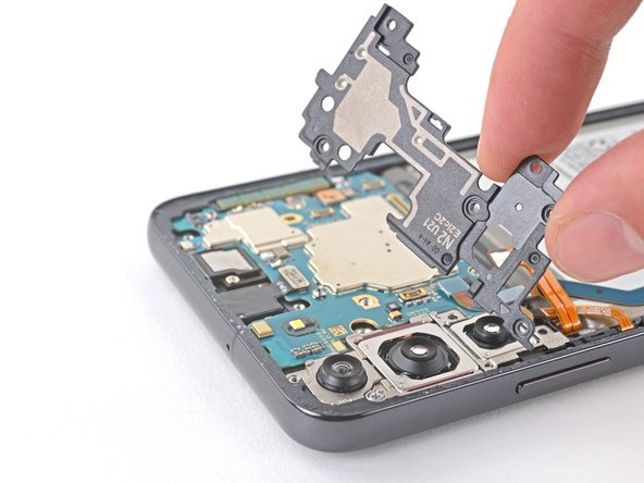
- Use your Phillips screwdriver to remove the four 3.5 mm screws securing the motherboard cover.
- Insert the pointed end of your spudger between the motherboard cover and the motherboard.
- The proper location is indicated by a triangle on the motherboard cover.
- Gently pry the motherboard cover up and off of the motherboard
- Remove the motherboard cover.
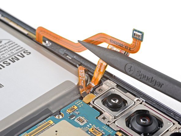
- Use your spudger to pry up and disconnect the left mmWave antenna from the motherboard.
- During reassembly, make sure the mmWave antenna cable is routed below the battery cable.
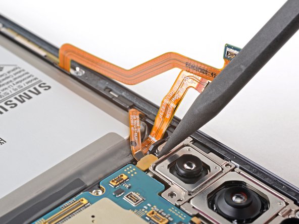
- Use your spudger to pry up and disconnect the right mmWave antenna from the motherboard.
- Reposition the battery and mmWave antenna cables to access the volume and power button press connector underneath.
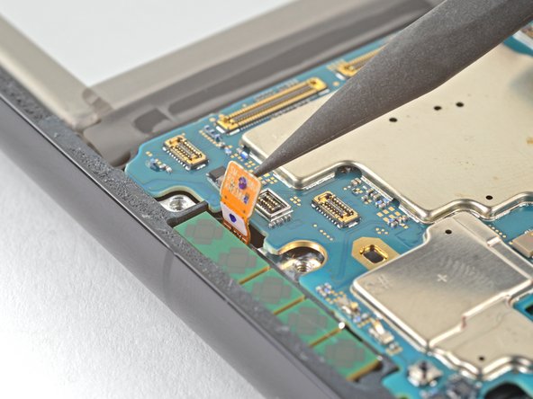
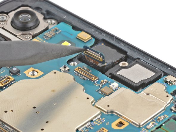
- Use the pointed end of your spudger to disconnect the volume and power buttons.
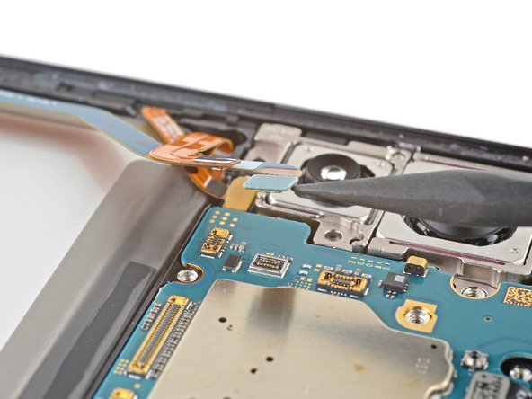
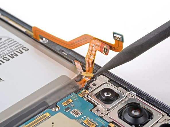
- Use the pointed end of your spudger to pry up and disconnect the front camera from the motherboard.
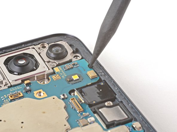
- Use your Phillips screwdriver to remove the 3.5 mm screw securing the camera module and motherboard to the frame.
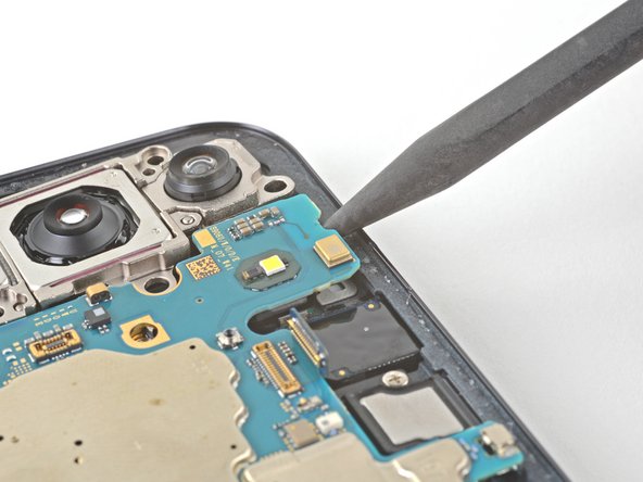
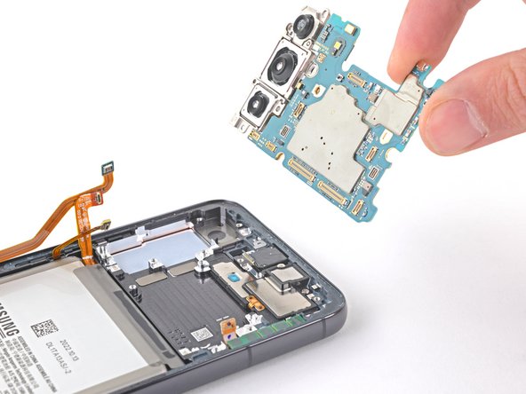
- Insert the pointed end of your spudger under the top left corner of the motherboard.
- This is the same location that was previously indicated by the triangle on the top antenna.
- Gently lift the motherboard out of the phone until you can grip it with your fingers.
- Be careful not to snag any cables when removing the motherboard. If you feel any resistance, check all cables to make sure they are clear of the motherboard.
- Remove the motherboard.
- During reassembly, make sure no cables are trapped underneath the motherboard.
- Prepare an iOpener and apply it to the front camera for three minutes.
- Place the iOpener on your work surface and lay the top edge of the screen on it to heat the camera from underneath.
- A hair dryer, heat gun, or hot plate may also be used, but be careful not to overheat the phone.
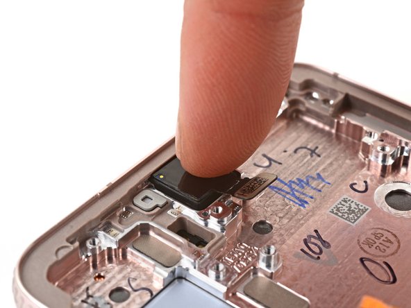
- Use the pointed end of your spudger to pry the front camera up and out of the frame.
- If the front camera is too difficult to remove, carefully use your SIM eject tool to scrape out the resin bonding it to the frame. Apply more heat if necessary.
- Use a pair of tweezers or your fingers to remove the front camera.
- During reassembly, prepare your new frame for the front-facing camera:
- Remove the black adhesive liner from the front-facing camera recess.
- Peel and remove the foam liner from the new frame.
- This liner isn't necessary for the repair.
- Before installing the front-facing camera, replace the adhesive in the frame:
- Remove the clear liner from the front-facing camera adhesive.
- Place the adhesive in the camera recess with its pull tab facing right.
- Remove the blue adhesive liner using its pull tab.
- Insert the front-facing camera into its recess in the frame and apply pressure to secure it.
- Use your Phillips screwdriver to remove the two 3.5 mm screws securing the left 5G mmWave antenna.
- Use the point of a spudger to pry up on the left 5G mmWave antenna bracket's lower screw tab until you can grip it with your tweezers.
- Use your tweezers to remove the left 5G mmWave antenna.
- Set the antenna aside. You'll reuse it during reassembly.
- Before reinstalling the lower 5G mmWave antenna, replace the bracket with a new one. If you don't have a new bracket, skip this step.
- Remove the antenna and connector from the old bracket.
- Remove the L-shaped adhesive liner from your new bracket.
- Place the antenna in the bracket's recess with the connector fed underneath the longer screw mount.
- Remove the thin adhesive liner on the outside of the bracket before installing it in the frame.
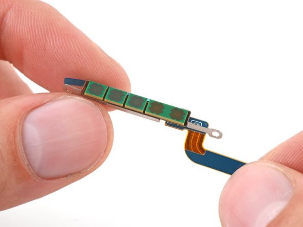
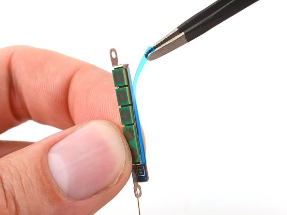
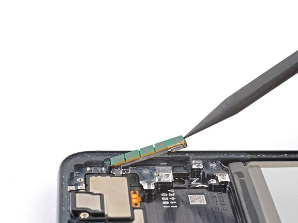
- Use the pointed end of your spudger to pry the right 5G mmWave antenna up until you separate its adhesive.
- If the antenna feels stuck, apply a Heated iOpener for two minutes to soften the adhesive.
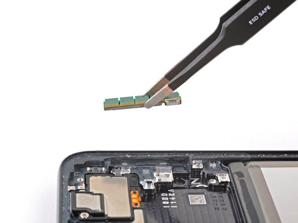
- Use tweezers or your fingers to remove the right 5G mmWave antenna.
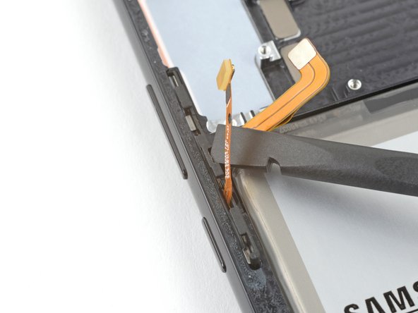
- Insert the corner of your spudger in the tab on the side button bracket.
- Twist the spudger upward to pry and loosen the side button bracket from its recess in the frame.
- During reassembly, press each button to make sure they "click." They should have the same sound and feel as before disassembly.
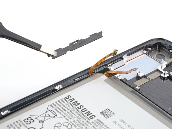
- Use blunt nose tweezers or your fingers to grab and remove the side button bracket.
- The button pad may come out with the bracket.
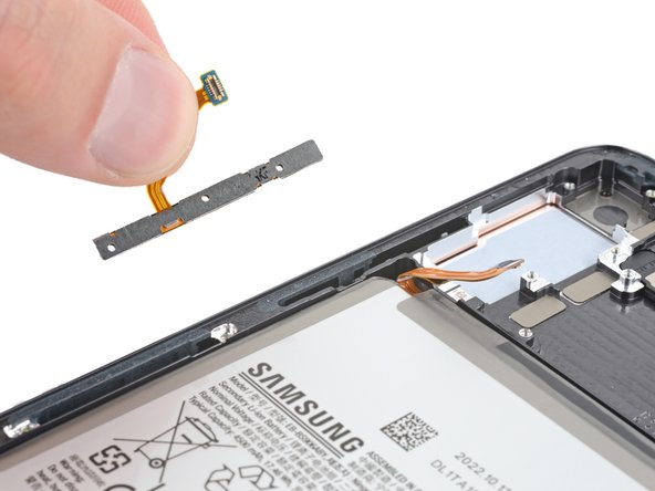
- Use your fingers to grab and remove the button pad.
- During reassembly, insert the button pad first. Then, insert the bracket against the back of the button pad. Together, they look like this.
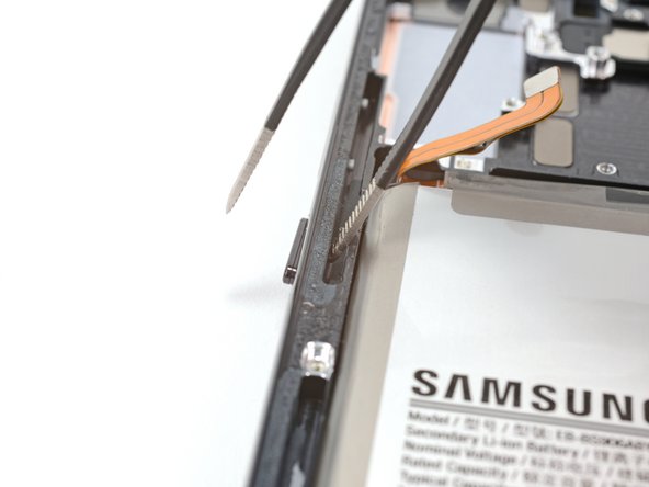
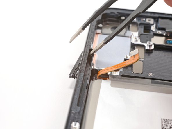
- Insert one arm of your blunt nose tweezers into the side button's recess.
- Push the power button's peg through the frame until you can grab the button with your fingers.
- If blunt nose tweezers don't reach deep enough into the recess, use the bent tip of a paperclip or a similarly-shaped object.
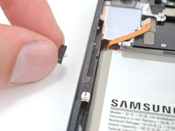
- Use your fingers to grab and remove the power button.
- Insert one arm of your blunt nose tweezers into the side button's recess.
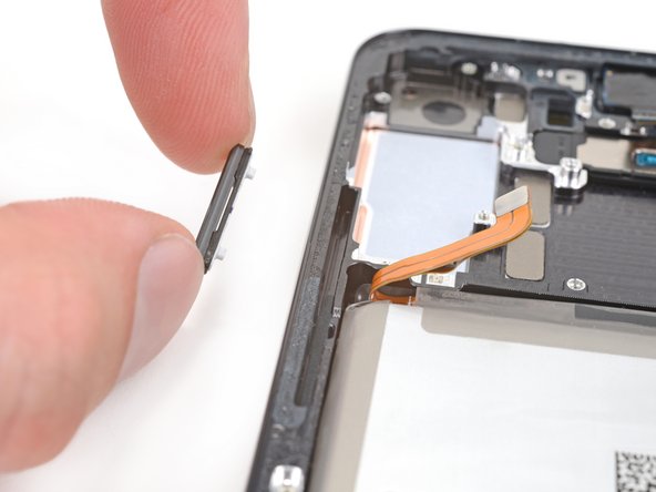
- Push both pegs of the volume buttons through the frame until you can grab the buttons with your fingers.
- If blunt nose tweezers don't reach deep enough into the recess, use the bent tip of a paperclip or a similar-shaped object.
- Use your fingers to grab and remove the volume buttons.
- Only the screen and battery assembly remains.
- Compare your new replacement part to the original part—you may need to transfer remaining components or remove adhesive backings from the new part before you install it.