Battery Disconnection
ID: 155468
Description: This is a prerequisite-only guide! This guide...
Steps:
- Insert a SIM card eject tool into the small hole in the SIM card tray, located on the upper left edge edge of the phone.
- Press firmly to eject the tray.
- Remove the SIM card tray from the phone.
- When reinserting the SIM card, make sure it's in the proper orientation inside the tray.
- A thin rubber gasket around the SIM tray provides water and dust protection. If this gasket is damaged or missing, replace the gasket or the entire SIM tray to protect your phone's internal components.
- The back cover of the Redmi Note 9T is held in place by plastic clips and mild adhesive around the camera cut-out. It might require some force to release the plastic clips.
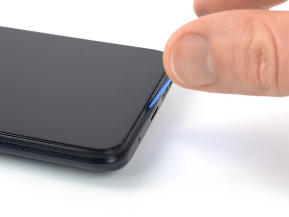
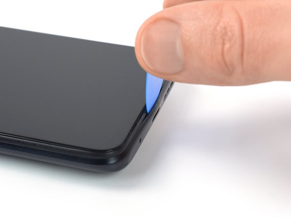
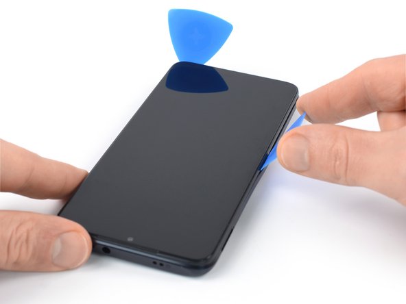
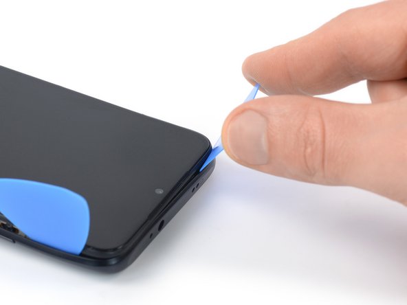
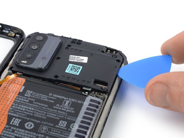
- Insert an opening pick in a steep angle between the display assembly and the back cover where the charging port is located. This might require some force.
- Make sure to insert the opening pick between the back cover and the display frame to avoid separating the screen from the frame.
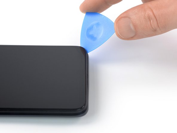
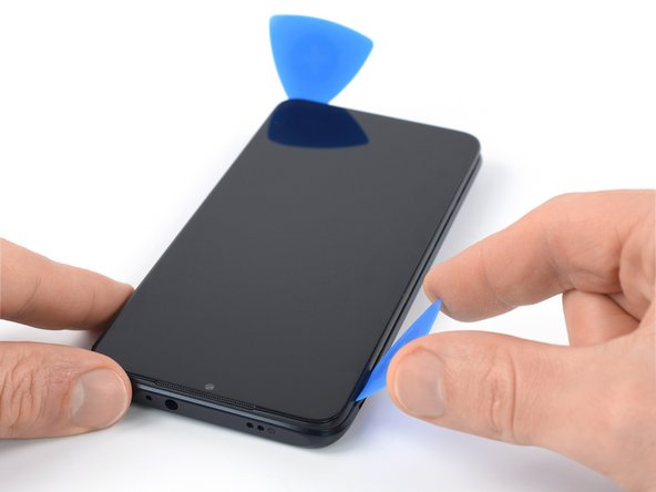
- Slide the opening pick to the bottom right corner to release the plastic clips holding the back cover in place.
- Leave the opening pick in the bottom right corner to prevent the clips from snapping back into place.
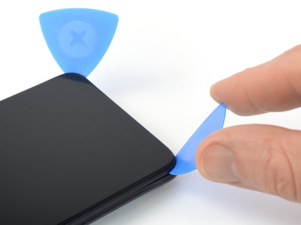
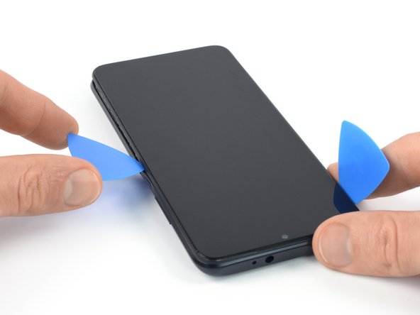
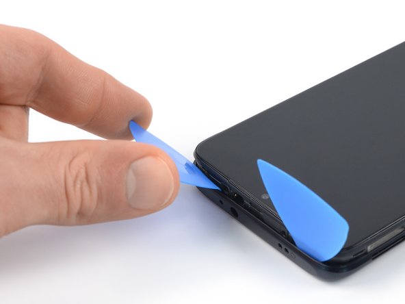
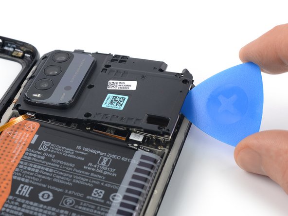
- Insert a second opening pick in a steep angle at the bottom edge of your phone.
- Slide the opening pick to the bottom left corner to release the plastic clips.
- Leave the opening pick in the bottom left corner to prevent the clips from snapping back into place.
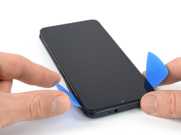
- Slide the bottom left opening pick along the left edge of your phone to release the plastic clips.
- Leave the opening pick in the top left corner to prevent the clips from snapping back into place.
- Slide the bottom right opening pick along the right edge of your phone to release the plastic clips.
- Leave the opening pick in the top right corner to prevent the clips from snapping back into place.
- Slide the left opening pick around the top left corner to release the top edge plastic clips.
- Slide the right opening pick around the top right corner to release the remaining plastic clips.
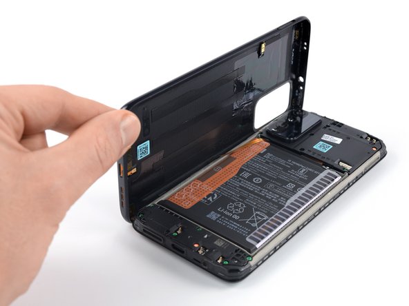
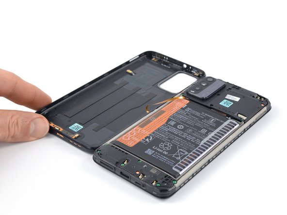
- Don't try to separate the phone assembly from the back cover all the way yet – the power and volume button cable is still connected to the motherboard.
- Carefully fold the back cover to the left side of the phone assembly like you would open the cover of a book.
- Take care not to strain or tear the power or volume button flex cable during this procedure.
- During reassembly align the back cover with the phone assembly and snap it back in its original position.
- Use a Phillips screwdriver to remove the ten 3.9 mm-long screws securing the motherboard cover.
- Insert an opening pick underneath the bottom right edge of the motherboard cover.
- Slide the opening pick along the right edge of the motherboard cover to release its plastic clips.
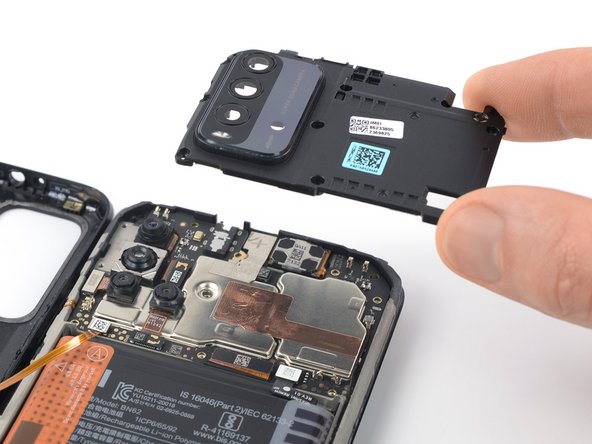
- Twist the opening pick sideways to pry up the motherboard cover.
- Remove the motherboard cover.
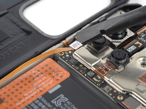
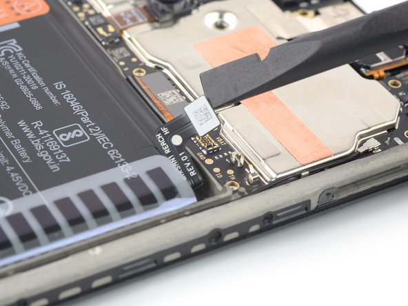
- Use a spudger to disconnect the home and volume button cable by prying the connector straight up from its socket.
- To re-attach press connectors like this one, carefully align and press down on one side until it clicks into place, then repeat on the other side. Don't press down on the middle. If the connector is misaligned, the pins can bend, causing permanent damage.
- Separate the back cover from the phone assembly.
- Use a spudger to disconnect the battery cable by prying the connector straight up from its socket.