HP Chromebook 11 G8 EE Motherboard Replacement
ID: 155523
Description: The motherboard is the primary piece of...
Steps:
- Use a Phillips #1 screwdriver to remove:
- Four 7 mm screws.
- Two 8 mm screws.
- Flip the device over and open the lid.
- Use a plastic opening tool to pry the keyboard assembly away from the bottom case, prying around the perimeter until it fully separates.
- Lift the keyboard assembly from the laptop towards you, away from the screen.
- Lift the keyboard ribbon lock bar and use tweezers to disconnect the keyboard ribbon from the motherboard.
- Lift the lock bar and use tweezers to remove the touchpad ribbon.
- Remove the keyboard.
- Peel back the film over the speaker's motherboard connector.
- Disconnect the speaker cable from the connector on the motherboard.
- Unseat the speaker cable from the routing channel of the battery.
- Remove the four 3.5 mm screws from the base enclosure with a Phillips #1 screwdriver.
- Lift the speakers off the base alignment pins to remove.
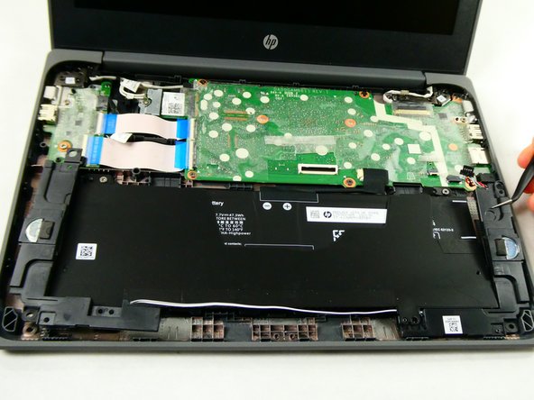
- Do not puncture or damage any parts of the battery.
- Disconnect the battery cable from the motherboard by pulling the connector straight out of its motherboard port.
- The speakers are removed in these images, but they don't need to be to replace the battery.
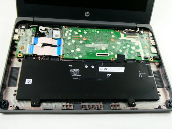
- Remove the four 3.5 mm Phillips #1 screws securing the battery.
- If you've already removed the speakers, you'll only need to remove the two screws on the top of the battery, near the motherboard.
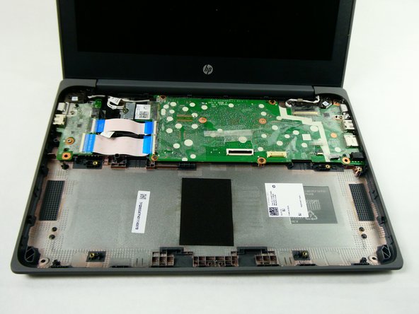
- Carefully lift the battery up and out.
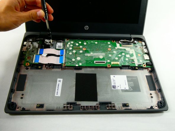
- Unscrew the single screw securing the Wi-Fi card/cover using a Phillips #1 screwdriver.
- Remove wireless antenna cables from the module using tweezers.
- Pull the Wi-Fi card out from its motherboard port using tweezers.
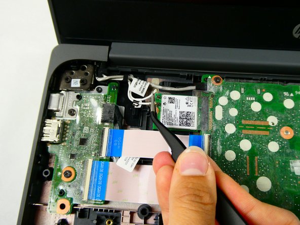
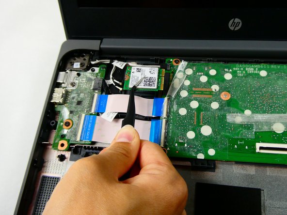
- Disconnect the webcam cable from the motherboard using tweezers.
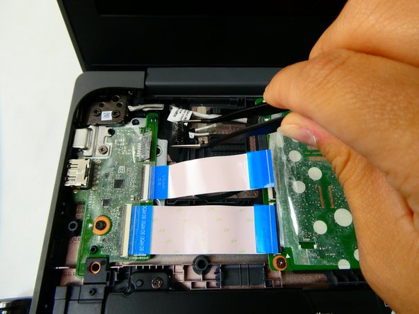
- Flip the two black lock bars on the ZIF connectors using tweezers.
- Disconnect both ribbon cables from the motherboard using the tweezers.
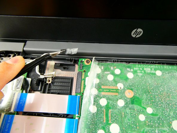
- Disconnect the power cable from the I/O board using tweezers.
- Peel back the film and lift the lock bar on the display panel cable with tweezers.
- Disconnect the display panel connector with tweezers.
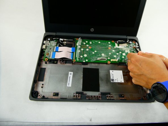
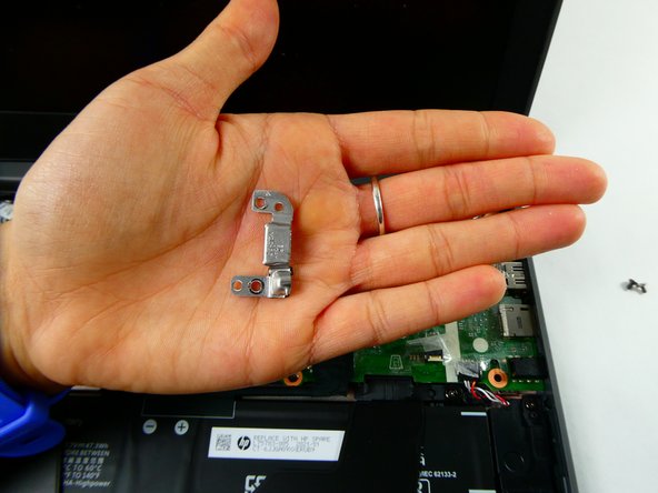
- Remove the six 3.5 mm screws with a Phillips #1 screwdriver.
- Lift the USB-C bracket off the motherboard.
- Lift the motherboard up and out.