DeLonghi ECAM Series power board repair
ID: 155600
Description: If the machine can no longer be switched on,...
Steps:
- Unplug the power cord!
- Remove all attachments such as water tank, pulp drawer, brew group.
- Turn the machine with the back facing you.
- Remove five Torx T20 security screws.
- A small hurdle: These screws have a pin in the middle, so the screwdriver must have a hole.
- Lift out the back.
- The following components are immediately visible:
- grinder
- pump
- flowmeter
- Also slide the cover - if not already done - on the water tank side backwards and remove it.
- The power board is located under the cover. It is fixed with four screws in the corners and connected with a lot of cables.
- Move the cables a bit to the side and unscrew the four Phillips screws in the corners.
- The cables have many different connectors and can almost not be confused. Make a special note of where the flat connectors are connected.
- The flat connectors can be disconnected more easily if you lift the cover in the corner of the device to the side.
- Lift the board out a few centimeters.
- Carefully loosen all connections. Some are secured with latches that you have to push away first.
- Here is the power board. The aluminum heat sink is only attached to the back of the board with three tabs. Straighten the three tabs with pliers and lift out the heat sink. Make sure it is clamped to a triac.
- When reassembling, make sure that you have applied enough thermal paste.
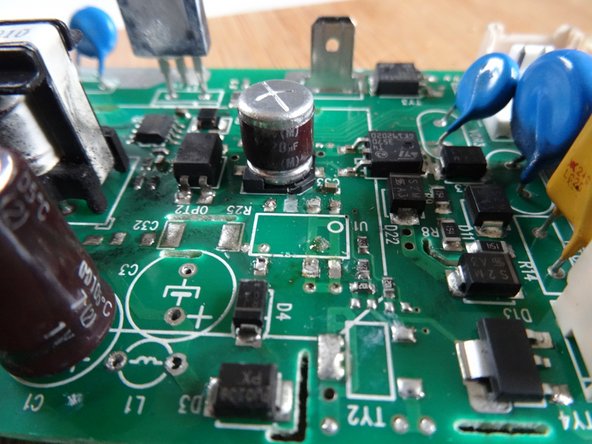
- Here are the critical components:
- R55: Resistor, 47 Ohm, 3 W
- L1: Inductance 1mH
- U1: Switcher IC LNK364GN
- First desolder these three components. Use a desoldering suction pump and/or desoldering wire. The desoldering of the IC is tricky, it is a SMD version. It's easier if you desolder the capacitor C3 beforehand as well, maybe you can also cut the pins of the IC carefully.
- Check the components:
- On this board, the inductor L1 was clearly defective, it was black, yellow beads were sweated out, the resistance was much too high, it should be in the range of 3 ohms.
- The 47 Ohm resistor R55 was infinite - nothing can work like that.
- The IC LNK364 was probably the trigger of the defect, between the two pins with the big gap the resistance should be some MegOhm, it was only a few Ohm.
- Check also the diode D1 (in installed condition), it should conduct only in one direction. If defective, replace it with a 1N4005. (Cathode, so minus in direction L1).
- Solder everything back in and drink a coffee first... other components could be defective as well...