Dell Inspiron 17" 7786 2-in-1 Keyboard Replacement
ID: 155612
Description: The integrated keyboard is a rather tedious...
Steps:
- Remove the eight M2 5mm screws that secure the base cover using a Phillips #0 screwdriver.
- Loosen the three captive screws that secure the base closer to the hinges.
- Do not attempt to remove the three captive screws! You need only to loosen them. They're supposed to stay on the base cover.
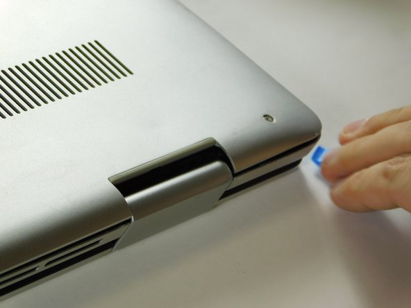
- Carefully pry the base cover using an iFixit opening tool in the crevice near the hinges. Guide the pick along the edges and slightly lift upwards as you go along.
- Do not start from the speaker end of the edges when opening, or you may cause further damage to your device!
- Carefully remove the base cover from the laptop.
- Detach the tab connecting the battery to the system board using your fingers or a pair of tweezers.
- Peel off the adhesive tab holding the cable to the device.
- Flip the device over. Press and hold the power button for a few seconds to discharge any leftover electrical current.
- You may leave the screen open if further repair is needed, or close it if you are only replacing the battery.
- Dell's official service manual does not mention of the 5th screw located near the middle edge of the battery closer to the touchpad.
- Flip the device back over.
- Remove five 3 mm screws that are securing the battery using a Phillips #0 screwdriver.
- Lift the battery upwards to remove it completely.
- Lift the cover to gain access to the memory module.
- Carefully open the securing clips on the end of each memory module slot until the module stick sticks up.
- Remove the memory module by sliding it out of the slot.
- Disconnect the CMOS battery cable from the motherboard.
- The battery may have a very strong adhesive keeping it from peeling off easily.
- Peel the battery off.
- Remove the screw holding down the small bracket for the wireless card using a Phillips #0 screwdriver.
- Remove the black wired connection from the port over the black triangle.
- Remove the wire with the white marking from the port above the white triangle.
- Pull the Wi-Fi card out of its slot.
- Detach the cable that connects the speakers to the system board.
- Starting with the speaker on the right hand area of the touch pad, carefully guide the speaker cabling out of the enclosure. You need only to lift upwards.
- Gently remove the I/O cable.
- Remove the fan cable from the motherboard.
- Remove two 3 mm screws that secure the fan using a Phillips #0 screwdriver.
- There is a little piece of tape/sticker on the fan that connects it to the heat sink. Gently remove this.
- Lift the fan off the palm rest assembly.
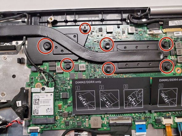
- Loosen seven 3 mm captive screws securing the heatsink to the motherboard using a Phillips #0 screwdriver.
- Lift the heatsink off the motherboard.
- Ensure that you have your device opened flat at a 180 degree angle. This will make removal easier.
- Locate the ribbon cables for the assembly on the right hand side marked "MB1" and "MB2."
- The "MB1" ribbon is locked with a copper/brass colored handle that must be lifted upwards. Then you can remove the ribbon by pulling it away from the socket.
- The "MB2" ribbon is locked in its socket with a black latch. Using a non-metallic precision tool (such as tweezers) lift the latch and pull away the MB2 cable.
- Remove the two screws holding down the assembly on the right hand area using a Phillips #00 screwdriver.
- Remove the screw protecting the endpoints of the NIC cables and NIC chip using a Phillips #0 screwdriver.
- Gently pull away the cabling from the NIC chip.
- The wires can be removed without removing the heat sink, though this is not advised if you are not familiar with the layout.
- Remove the two screws holding down the bracket of the assembly on the left hand side using a Phillips #0 screwdriver.
- Lift the display assembly upwards away from the palm/main assembly.
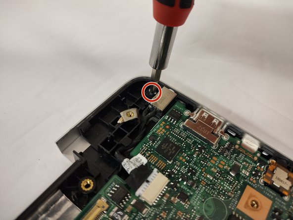
- Remove the single 3 mm screw that secures the port using a Phillips #0 screwdriver.
- Disconnect the cable from the port by gently wiggling and pushing the plug away from the port.
- Pull the disconnected cable upwards, and the rest of the power port will follow.
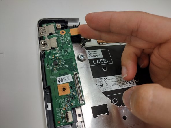
- Lift the latch holding down the ribbon cable on the I/O board, then pull it away using the blue tab.
- Lift the I/O board upwards to remove it from the assembly.
- Lift the latch holding down the ribbon cable. Remove the cable away from the port.
- Remove the screw holding down the button in place using a Phillips #0 screwdriver.
- Grabbing the cushioning of the button, lift it upwards from the assembly.
- Disconnect all cables from the system board:
- Keyboard cables with latches
- HDD cable with latch
- I/O cable that must be lifted or carefully pried away from the board using a spudger
- It is intended to pull on the black tab of the plug to remove the cable, though it is prone to ripping when doing so.
- Disconnect the touch pad cable with the latch.
- Remove the two screws holding down the system board using a Phillips #0 screwdriver:
- One screw is located above the RAM slot to the right.
- Another screw is located next to the I/O cable near the edge on the left.
- Lift the motherboard out of the laptop.
- Lift the latch holding down the ribbon cable connected to the touch pad.
- When inserting the cable back, ensure that it goes under the white indents.
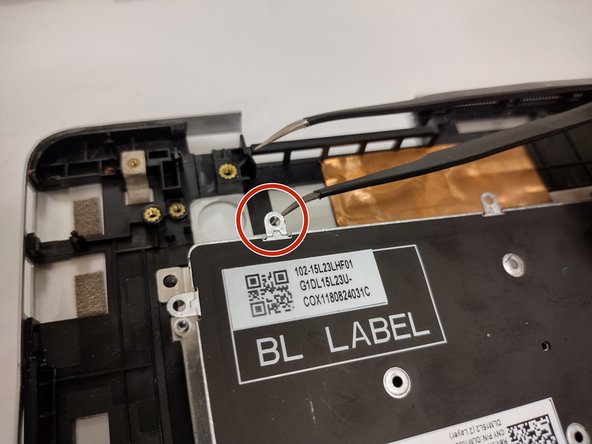
- Remove the three screws holding down the bracket on the bottom portion of the touch pad using a Phillips #0 screwdriver.
- Remove the four screws holding down the bracket on the upper portion of the touch pad using a Phillips #0 screwdriver.
- Remove the bracket on the bottom portion of the touchpad by carefully peeling it away, as it is held by adhesives, then set it aside.
- Pull the small adhesive tabs to lift the touch pad away from the assembly.
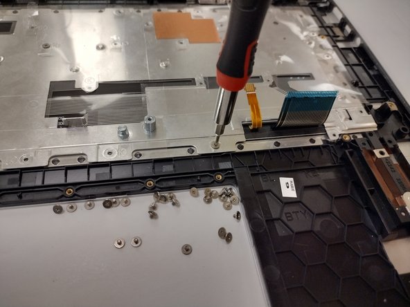
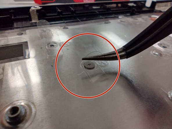
- Remove all 32 screws securing the metal plate to the assembly using a Phillips #0 screwdriver.
- Dell's official manual mentions removing the tape holding the metal plate down. This is optional since you can pick and lift the outlines of small tabs covering the screws of the right hand area of the assembly.
- The metal plate can be easily bent. Ensure you do not grip too hard, or allow it to be bent.
- Lift the metal plate upwards by the edge, or use the metal indents used for the screws.
- Remove the five screws securing the keyboard to the assembly using the Phillips #000 screwdriver.
- The keyboard itself is light and rather flimsy. Handle it with care.
- Carefully lift the keyboard from the upper edge away from the assembly.