Dell Inspiron 17" 7786 2-in-1 Charging Port Replacement
ID: 155613
Description: It may be a collective thought to think that...
Steps:
- Remove the eight M2 5mm screws that secure the base cover using a Phillips #0 screwdriver.
- Loosen the three captive screws that secure the base closer to the hinges.
- Do not attempt to remove the three captive screws! You need only to loosen them. They're supposed to stay on the base cover.
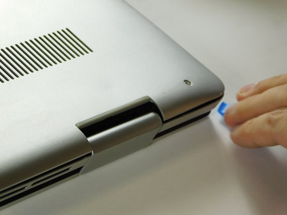
- Carefully pry the base cover using an iFixit opening tool in the crevice near the hinges. Guide the pick along the edges and slightly lift upwards as you go along.
- Do not start from the speaker end of the edges when opening, or you may cause further damage to your device!
- Carefully remove the base cover from the laptop.
- Remove the screw holding down the small bracket for the wireless card using a Phillips #0 screwdriver.
- Remove the black wired connection from the port over the black triangle.
- Remove the wire with the white marking from the port above the white triangle.
- Pull the Wi-Fi card out of its slot.
- Gently remove the I/O cable.
- Remove the fan cable from the motherboard.
- Remove two 3 mm screws that secure the fan using a Phillips #0 screwdriver.
- There is a little piece of tape/sticker on the fan that connects it to the heat sink. Gently remove this.
- Lift the fan off the palm rest assembly.
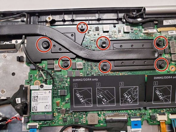
- Loosen seven 3 mm captive screws securing the heatsink to the motherboard using a Phillips #0 screwdriver.
- Lift the heatsink off the motherboard.
- Ensure that you have your device opened flat at a 180 degree angle. This will make removal easier.
- Locate the ribbon cables for the assembly on the right hand side marked "MB1" and "MB2."
- The "MB1" ribbon is locked with a copper/brass colored handle that must be lifted upwards. Then you can remove the ribbon by pulling it away from the socket.
- The "MB2" ribbon is locked in its socket with a black latch. Using a non-metallic precision tool (such as tweezers) lift the latch and pull away the MB2 cable.
- Remove the two screws holding down the assembly on the right hand area using a Phillips #00 screwdriver.
- Remove the screw protecting the endpoints of the NIC cables and NIC chip using a Phillips #0 screwdriver.
- Gently pull away the cabling from the NIC chip.
- The wires can be removed without removing the heat sink, though this is not advised if you are not familiar with the layout.
- Remove the two screws holding down the bracket of the assembly on the left hand side using a Phillips #0 screwdriver.
- Lift the display assembly upwards away from the palm/main assembly.
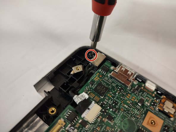
- Remove the single 3 mm screw that secures the port using a Phillips #0 screwdriver.
- Disconnect the cable from the port by gently wiggling and pushing the plug away from the port.
- Pull the disconnected cable upwards, and the rest of the power port will follow.