Microsoft Surface Laptop 5 (15-inch) Screen Replacement
ID: 157315
Description: Follow this guide to replace the screen in your...
Steps:
- Allow your laptop's battery to drain below 25% before starting this repair. A charged battery may catch fire if damaged.
- Unplug all cables and fully shut down your laptop.
- Close the screen and lay your laptop down with the rear case facing up to access the four rubber feet.
- Each foot has a recess to help pry it from the laptop:
- The back feet recesses are closest to the back edge of the laptop.
- The front feet recesses are closest to the front edge of the laptop.
- Insert one arm of your tweezers into the recess of one of the feet.
- Twist your tweezers and pry up to separate the adhesive and unclip the foot from the laptop.
- The feet eject very quickly—be careful not to lose them.
- Remove the foot.
- Repeat this process on the remaining feet.
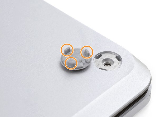
- This laptop has two different types of feet. During reassembly, make sure the feet go in their correct recesses.
- The rear feet have a single center clip.
- The front feet have three clips and can only be reinserted one way.
- Press the feet into their recesses to secure them to the frame.
- If the existing feet no longer adhere to the frame, remove the old adhesive and apply a small amount of Tesa Tape where the old adhesive was.
- If the feet are damaged or worn out, use 8 mm rubber furniture pads:
- Peel a pad away from its backing.
- Align the pad over a foot cavity and press down to secure it.
- These screws strip easily. Apply constant, downward force to prevent stripping.
- Use a T5 Torx driver to remove the four 3 mm screws securing the upper case.
- Throughout this repair, keep track of each screw and make sure it goes back exactly where it came from.
- Flip your laptop over and fully open the screen.
- The upper case is secured by magnets.
- Grip the top edge of the upper case above the keyboard and lift straight up to release it.
- Don't try to completely remove the upper case, as it's still connected to the laptop by a cable.
- Lift the bottom edge of the upper case up and away from the laptop, taking care to not strain the ribbon cable underneath.
- During reassembly, lower the upper case onto the lower case until the magnets snap into place and it lays flat.
- Check that the upper case sits flush around the entire perimeter. Any gaps between the upper and lower case near the screen could damage the screen as it closes.
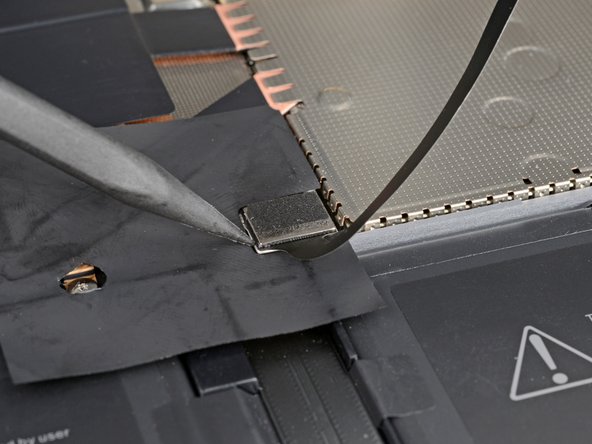
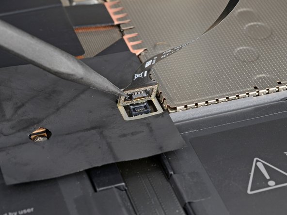
- The keyboard and touchpad cable connects the upper case to the laptop.
- Insert the pointed end of a spudger under one edge of the magnet connector and pry up to disconnect it.
- To reconnect the cable, align the magnet connector over its socket with the cable facing the bottom of the laptop. Press down on the connector to secure it.
- Remove the upper case and set it keyboard-side down on a clean surface.
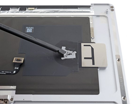
- Your SSD has thermal paste that forms a bond to the upper case.
- During reassembly:
- Use the flat end of your spudger to scrape away old thermal paste from the top of the SSD and the underside of the upper case.
- Apply a few drops of highly-concentrated isopropyl alcohol (over 90%) to the SSD and upper case. Wipe away the residue using a lint-free or microfiber cloth.
- Replace the thermal pad with one that's the same size as the SSD sticker.
- Alternatively, you can apply a bead of thermal paste directly to the SSD's label. Use the dot method with a bead slightly larger than the screw head securing the SSD.
- Use a T5 Torx driver to remove the 2.7 mm screw securing the SSD.
- With the screw removed, the SSD pops up at a shallow angle.
- Removing the SSD also functions as a battery disconnect.
- Pull the SSD out of its socket and remove it.
- Don't pull up at a sharp angle, as this could damage the SSD and its socket.
- During reassembly, insert the SSD at a slight angle.
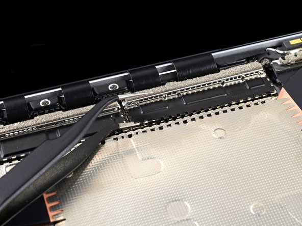
- Insert one arm of your tweezers under the corner of the right display cable shield.
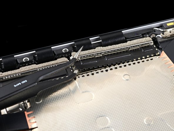
- Gently pry up to release the clips securing the shield.
- Try not to deform the shield too much. You'll need to reinstall it during reassembly.
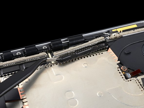
- Repeat this process around the left, right, and bottom edges of the shield until you can remove it.
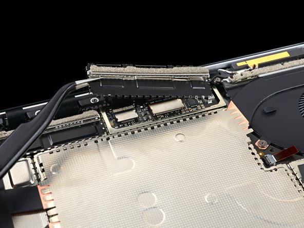
- Pull the right display cable shield towards the bottom of the laptop to free it from its recess.
- Remove the shield.
- Repeat the previous two steps to remove the left display cable shield.
- During reassembly, use the flat end of a spudger to gently push the display cables back into their cavity in the lower case after reconnecting the press connectors.
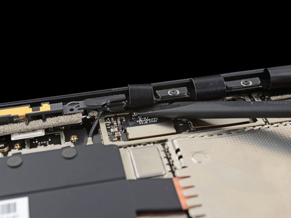
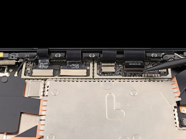
- Use the flat end of a spudger to pry up and disconnect all four display cable press connectors.
- To re-attach press connectors like this one, carefully align and press down on one side until it clicks into place, then repeat on the other side. Do not press down on the middle. If the connector is misaligned, the pins can bend and cause permanent damage.
- Fully open the screen.
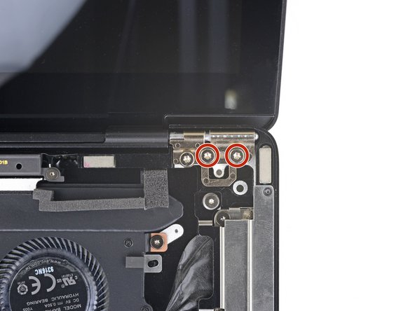
- When removing the hinge screws, make sure to hold the screen steady as it will become loose as the screws are removed.
- While holding the screen steady, use a T6 Torx driver to remove the four outermost 5.9 mm screws securing the screen (two on each side).
- Both hinges should have one remaining screw (two total). Leave these screws in place.
- Close the screen until it's almost vertical.
- During reassembly, with the first two hinge screws tightened in place, the screen is free to tilt open for installation of the remaining four hinge screws.
- While holding the screen steady, use a T6 Torx driver to remove the two remaining 5.9 mm screws securing the screen (one on each side).
- If the screen is exactly perpendicular to the lower case, the screwdriver handle may hit the screen during removal. If you're having trouble, tilt the screen back enough to clear the driver.
- Lift the screen straight up and remove it.
- During reassembly, ensure the replacement screen hinges are at a 90 degree angle with the screen.