Mac Mini M2 Teardown
ID: 157365
Description: Teardown on the M2 Mac Mini (early 2023). The...
Steps:
- This teardown applies to the base M2 model of Mac mini. This guide uses the following specs:
- System on Chip M2 8-core CPU with 4 performance cores and 4 efficiency cores
- 8 GB of memory
- Two Thunderbolt 4 ports with support for 6K resolution at 60 Hz.
- 256 GB of SSD Storage.
- The overall exterior design hasn't changed too drastically since the M1 Mac mini, although the M2 Mac mini is slightly smaller.
- On the back of the unit, we find our I/O ports. The base M2 has two Thunderbolt 4 ports, although the M2 Pro model has four ports. We also have two USB-A ports, HDMI 2.0 port, a Gigabit ethernet port, and a standard 3.5 mm headphone jack.
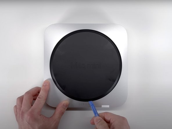
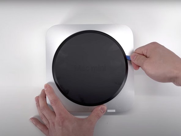
- Flipping the device over, we can see the iconic bottom cover with the Mac mini logo molded into it. Removing the cover can be done easily enough with an Opening Tool, although Apple has recommended using a Spudger for this in their guide for the M1 Mac mini.
- With the cover removed, we can see the antenna plate. This is held down with six Torx T6 security screws, which can be removed with the appropriate screwdriver.
- Carefully moving the plate to the side, we get just enough space to expose the antenna coaxial cable held down with a grounding clip and another T6 screw.
- With the screw removed, a Spudger can be used to dislodge the antenna plate. Alternatively you can use an Opening Tool for this.
- With the antenna plate removed, we can get access to the single fan as well as the PRAM battery.
- The fan can be removed with minimal fuss after loosening the four T5 Torx screws.
- The fan itself is really similar to the OEM fan on the M1, and it wouldn't be surprising is the two shared the same specs.
- It is worth pointing out that with the fan removed it becomes abundantly obvious that there is a lot of empty space, especially when you consider that whole logic board only takes up about half of the full volume of the device.
- While it is really cool that Apple can cram that much power into such a small board, they missed the opportunity to include some additional I/O features, or significantly slim down the overall design of the mini.
- Once the fan is removed we can unplug the flex cable for the LED indicator light by flipping up the ZIF connector, and removing the cable from its housing.
- We can also remove the power supply cable by peeling off the polyester film from the top of the connector, and carefully pulling the cable out of the connector.
- The logic board is only held down by two Torx T10 screws.
- Once the screws are removed we can slide the board out of its housing with no fuss.
- To remove the power supply from the housing first remove the three T6 screws from the power supply.
- Using a set of tweezers, remove the retention clip from under the AC inlet. This will allow us to rotate the inlet. Rotating the inlet 90 degrees counterclockwise will allow us to slide the power supply out of the housing.
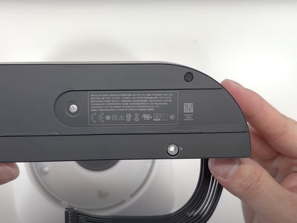
- The power supply itself is for the most part unmarked, save for the small label on the bottom giving its specs.
- Part Number: 614-00045
- Input: 100-240 V, 50-60 Hz, 2.0 A
- Output: 12 V, 12.5 A
- Moving right on to the logic board assembly, the overall layout of components remains unchanged. Everything from the speaker to the I/O wall, and even the heat sync has the same layout as the M1 mini.
- The speaker is held down by two T6 screws.
- Moving the speaker over shows the speaker's connector on the logic board. Using an opening tool we can free the speaker from the connector.
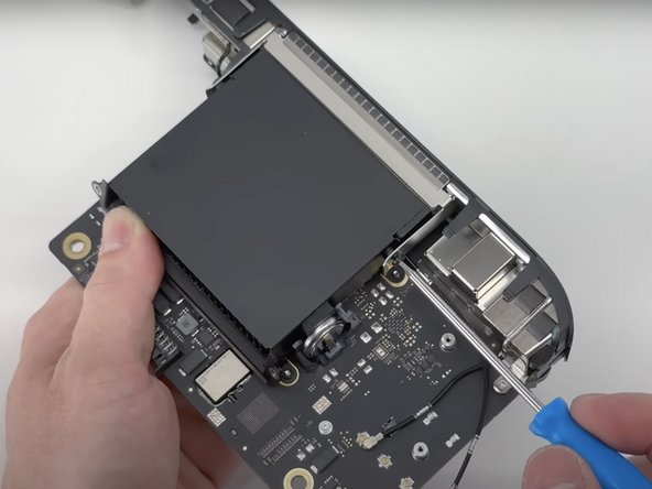
- The Bluetooth antenna is a simple coaxial connection. This is undone with an opening tool.
- There are also three grounding clips that hold the cables in place. These are also easily undone with the opening tool.
- Both cables thread through a channel underneath the heat sink. Once these cables are freed from the grounding clips they can be pulled through the channel.
- On the back, we find the connection for the power button. This is a simple ZIF connection that can be easily undone using the opening tool to lift the clip.
- Once all the cables have been undone, the only thing that is holding the I/O wall in place is five T6 Torx screws. Once the screw is attached to the logic board, the other four are attached to both sides of the heat sink's shroud.
- The final component that can be removed is the heat sink shroud, and the heat sink itself. Both sets of screws are T6 Torx screws.
- All four screws for the shroud are each covered by a small rubber and are adhered to the screws themselves.
- The heat sink is attached to the logic board with four screws, along with two brackets.
- Interestingly, Apple didn't feel the need to tell us how to remove either of the components in the M1 guide. Yes, heat sinks don't "go bad“, thermal paste typically dries out after five years. Either Apple is confident that their thermal paste will last the lifetime of the device, or they expect you to buy a new Mac in 5 years.
- Dust has also been a culprit of cooling issues, so it probably wouldn't be a horrible idea to get in there with a dust blower.
- In typical Apple fashion, we see a small amount of thermal paste covering the CPU. Cleaning off the paste reveals Apple's signature logo.
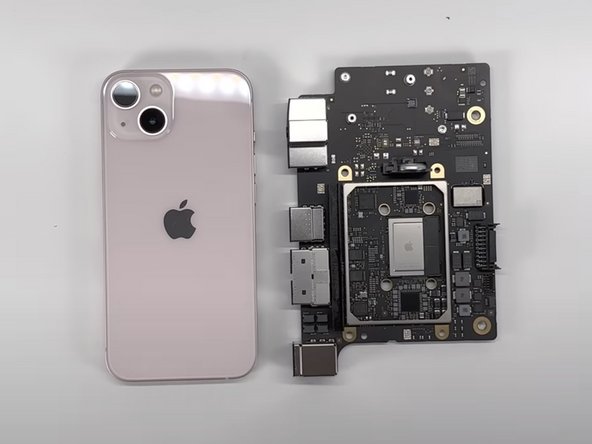
- The overall footprint of the board itself is just a little bit wider than the iPhone 13.
- 64-bit M2 8-core SoC (system on a chip).
- 8 GB (2 x 4 GB) LPDDR5 SDRAM memory
- PRAM battery housing
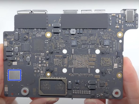
- 256 GB NAND Flash
- PMIC Ethernet Controller
- Wi-Fi/Bluetooth module
- No tough adhesive holds the M2 Mac mini or its components hostage.
- Use of a few common tools, disassembly is straight-forward.
- The disassembly does not differ significantly from the M1 mini, which makes many repairs familiar.
- Apple's poor thermal paste job might prove to be a problem later on.
- All I/O ports are soldered directly to the logic board. If one breaks then the whole board needs to be replaced.
- Upgrading components like storage or memory are almost impossible due to the integration with the processor.
- The CPU and storage are both soldered to the logic board and not user-upgradeable.