Nokia G22 Screen Assembly Replacement
ID: 157507
Description: Use this guide to replace a broken screen on...
Steps:
- Insert a SIM eject tool, bit, or a straightened paper clip into the small hole on the SIM card tray on the upper left edge of the phone.
- Press firmly to eject the tray.
- Remove the SIM card tray.
- When installing either a SIM card or a microSD card, make sure they're in the correct orientation and sitting completely flush with the edges of the tray before reinserting the tray into the phone.
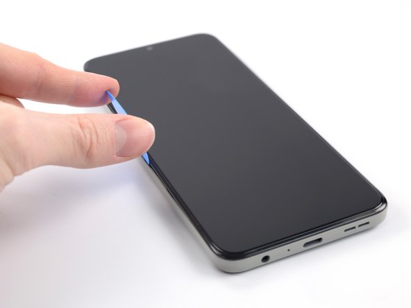
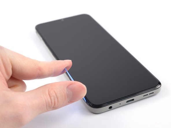
- The back cover of the phone is held in place by plastic clips.
- Insert an opening pick under the small notch in the SIM card tray slot.
- Position the opening pick at a steep downward angle between the back cover and the screen assembly.
- Slide the opening pick down the left edge of the phone to release the plastic clips.
- Turn the opening pick around the corner and continue to slide it along the bottom edge to release the plastic clips.
- Slide the opening pick up the right edge to continue releasing the plastic clips.
- Slide the opening pick along the top edge to release the remaining plastic clips.
- Don't try to fully remove the back cover just yet, as it's still connected to the phone.
- With the phone laying screen-side down, carefully lift the right edge of the back cover, opening it like a book.
- Take care not to strain or tear the attached fingerprint reader cable during this procedure.
- Lay the back cover next to the phone.
- Use a Phillips screwdriver to remove the 3.8 mm‑long screw securing the fingerprint reader bracket.
- Use a pair of tweezers or your fingers to remove the fingerprint reader bracket.
- Take care not to puncture the battery with your tool—a punctured or bent battery may leak dangerous chemicals or cause a fire.
- During reassembly, make sure to align the fingerprint reader bracket correctly and push the small metal edge back into its recess under the motherboard cover.
- Use the flat end of a spudger to disconnect the fingerprint reader by prying the connector straight up from its socket.
- To re-attach press connectors like this one, carefully align and press down on one side until it clicks into place, then repeat on the other side. Do not press down on the middle. If the connector is misaligned, the pins can bend and cause permanent damage.
- Remove the back cover.
- There is a white sticker covering one of the top screws. Pierce through it with the screwdriver or use tweezers to remove it.
- Use a Phillips screwdriver to remove the eleven 3.8 mm-long screws securing the motherboard cover.
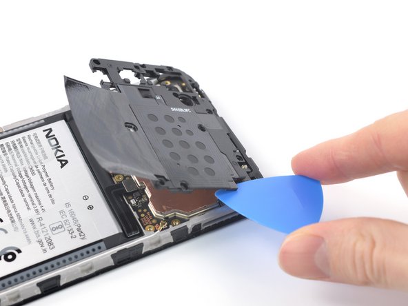
- The motherboard cover is further held in place by plastic clips.
- Insert an opening pick under the right edge of the motherboard cover to release its plastic clips.
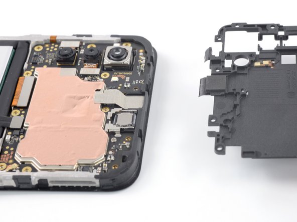
- Flip the motherboard cover over the top edge of the phone.
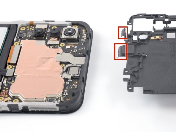
- The motherboard cover has two short adhesive tapes wrapped around the top edge and onto the frame.
- Pull the motherboard cover away from the frame to separate the adhesive tape and remove it.
- During reassembly, fold the adhesive strips onto the frame after snapping the motherboard cover back in place.
- Use the flat end of a spudger to disconnect the battery cable by prying the connector straight up from its socket.
- There is a white sticker covering one of the top screws. Pierce through it with the screwdriver or use tweezers to remove it.
- Use a Phillips screwdriver to remove the eight 3.8 mm-long screws securing the loudspeaker.
- Insert an opening pick underneath the right edge of the loudspeaker.
- Twist the opening pick to release loudspeaker from the plastic clips holding it in place.
- Use your fingers or a pair of tweezers to remove the loudspeaker.
- Use the flat end of a spudger to disconnect the display cable by prying the connector straight up from its socket.
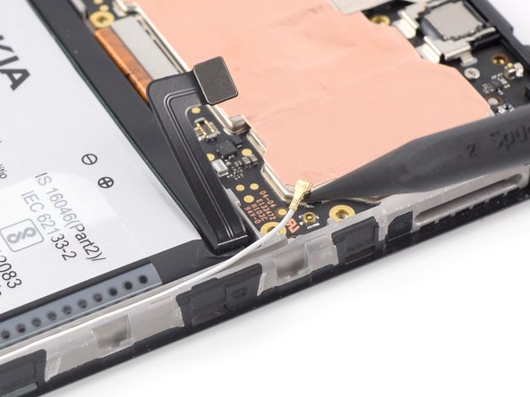
- Use the pointed end of a spudger to disconnect the antenna cable by prying the connector straight up from its socket on the motherboard.
- Use a pair of tweezers or your fingers to lift the antenna cable out of its recess in the frame.
- During reassembly, connect the antenna cable to the motherboard before reseating the antenna cable into its recess.
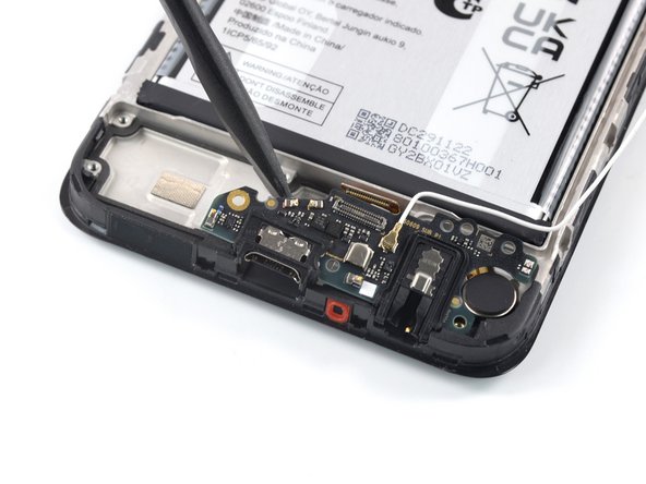
- Use a Phillips screwdriver to remove the 2.8 mm‑long screw securing the charging port assembly.
- Insert the flat end of a spudger underneath the top edge of the charging port assembly.
- Pry up the charging port assembly by twisting the spudger until you can grip it with your fingers.
- Remove the charging port assembly.
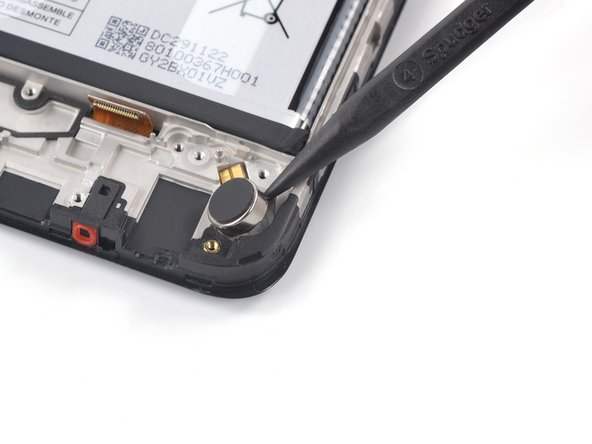
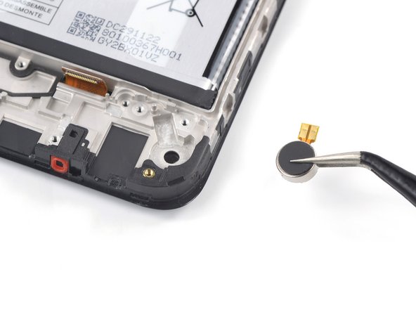
- The vibration motor is held in place with mild adhesive.
- Insert the pointed end of a spudger into the small recess on the upper right side of the vibration motor.
- Pivot the spudger up to pry up the vibration motor off of the adhesive securing it underneath.
- Use a pair of tweezers or your fingers to remove the vibration motor.
- During reassembly, you can reuse the old adhesive if it's still sticky. If not, replace it with new custom cut adhesive, such as Tesa Tape.
- Use the flat end of a spudger to disconnect the display cable by prying the connector up from its socket.
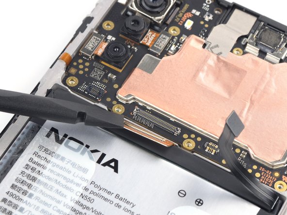
- Use a Phillips screwdriver to remove the 2.8 mm‑long screw securing the motherboard.
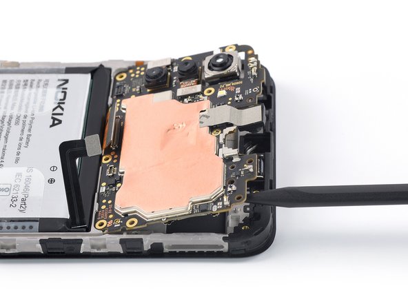
- Insert the pointed end of a spudger underneath the top right corner of the motherboard.
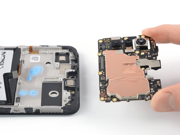
- Pry the motherboard up until you can grip it with your fingers.
- Remove the motherboard.
- During reassembly apply small beads of thermal paste to the marked areas on the new screen assembly. See this generic guide for detailed steps on how to prepare the motherboard and apply the paste.
- The earpiece speaker is secured to the frame with mild adhesive.
- Insert the flat end of a spudger underneath the bottom left corner of the earpiece speaker and pry it out of its recess.
- Remove the earpiece speaker.
- During reassembly, make sure the gold contact springs on the earpiece speaker are facing up and closer to the bottom edge of the phone before readhering it to the frame.
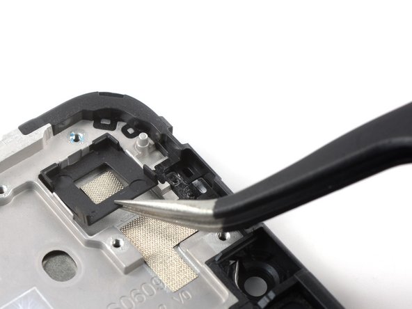
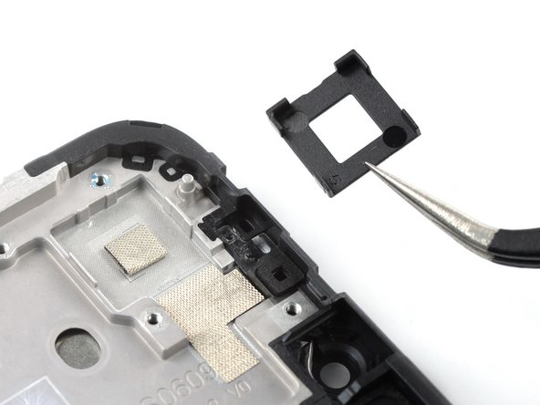
- If your new screen assembly comes with a camera bracket you can skip this step. If not you’ll need to transfer the bracket or apply a new one.
- Use a pair of tweezers to remove the black camera bracket.
- The camera bracket is held in place with mild adhesive.
- During reassembly, transfer the old camera bracket or install a new bracket for the new screen assembly.
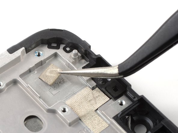
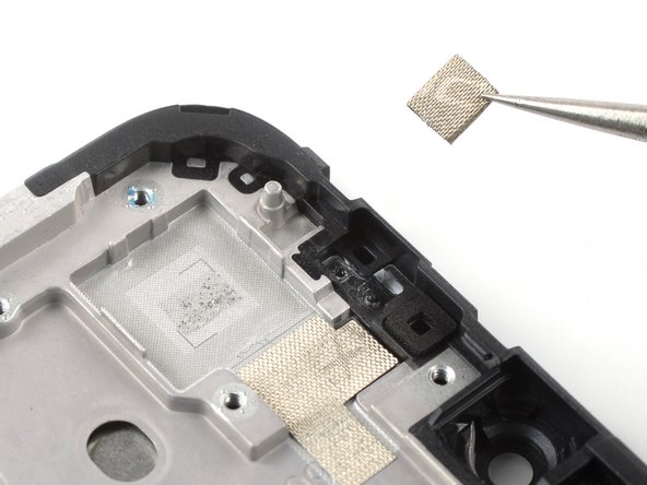
- If your new screen assembly comes with a foam pad you can skip this step. If not you’ll need to transfer the old pad or apply a new one.
- Use a pair of tweezers to carefully peel the foam off of the frame to remove it.
- The foam pad in the camera recess is held in place with mild adhesive.
- During reassembly, transfer the old foam pad or install a new one for the new screen assembly. You can install the camera bracket first to help orient the foam pad.
- Be extra careful to not puncture, bend, or deform the battery during the next few steps—a damaged battery may leak dangerous chemicals or cause a fire.
- Use your fingers to peel the two outer adhesive tabs off of the battery.
- The battery in the Nokia G22 is secured with adhesive. A pull tab is provided to separate the adhesive and remove the battery.
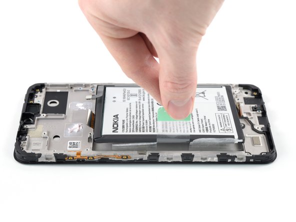
- Use your fingers to peel the center green pull tab off of the battery.
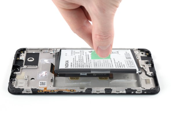
- Using one hand to hold the phone down, use your other hand to slowly and steadily lift the center green pull tab up to separate the adhesive securing the battery underneath.
- If the green pull tab should rip, you can use the outer tabs to pull out the battery including the adhesive film underneath. Be aware that therefore this will take more time and probably some heat to soften the adhesive.
- If you have any difficulties with stubborn battery adhesive, you can contact "Nokia phones support".
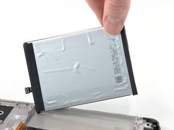
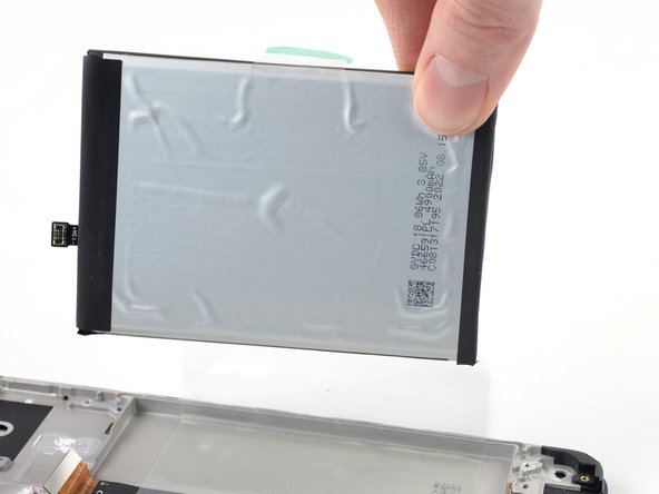
- Peel the battery off of the adhesive film and remove it.
- Grab the bottom right edge of the leftover adhesive film and pull it towards the top of the phone with steady force to remove it.
- During reassembly, follow these instructions to apply a new battery adhesive film:
- Remove the battery adhesive film from its liners and apply it to the battery.
- Align the bottom edge of the battery (the edge without adhesive) with the bottom edge of the recess.
- Lower the battery with its film down and press firmly to secure it in place.
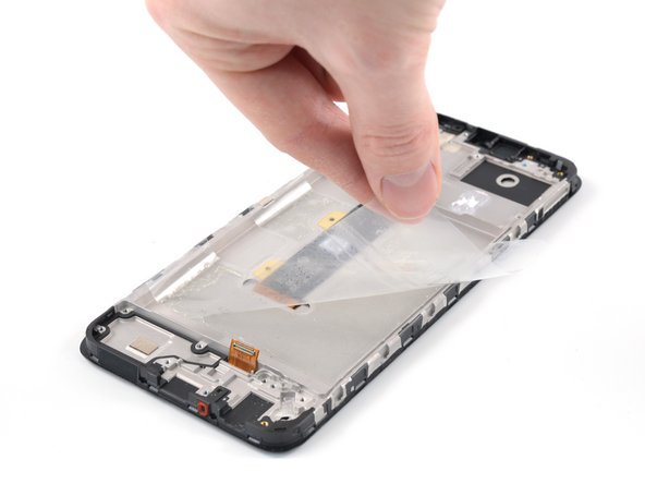
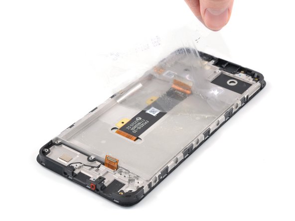
- Only the screen assembly remains.
- During reassembly, compare your new replacement assembly to the original part:
- If your part comes with battery adhesive pre-installed, remove its plastic liners before continuing to the previous step.
- If your part has no battery adhesive, remove the clear liner on the pre-cut battery adhesive and apply the sticky section to the battery well. Remove the opaque liner before continuing to the previous step.
- If you're reusing your original battery, carefully inspect it for any signs of physical damage. If it's bent, creased, dented or scratched, replace it with a new battery. Installing a damaged battery is a safety hazard.