Sony Alpha NEX-3N Disassembly and Shutter Repair
ID: 157565
Description: Sony Alpha NEX Cameras Shutter Error Repair...
Steps:
- Start with removing the SD card, battery, and the lens from the camera.
- Remove the marked metric screws using a Philips #00 screwdriver. They are all identical.
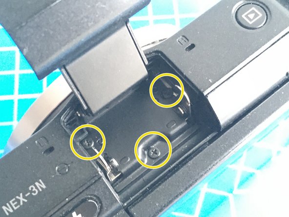
- Remove the marked metric screws under the SD card door and the flash unit, using a Philips #00 screwdriver. They are all identical.
- Gently pry the flash button assembly away from the camera, remove the cover as seen in the photos.
- Gently remove the rear plastic cover by prying it off starting from the bottom edges.
- Free the LCD unit by removing two small black metric screws using Philips #00 screwdriver.
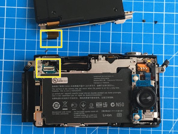
- Gently unlock the ZIF connector as marked to remove the flat flex cable.
- Lift the locking tab up using a pair of tweezers and slide the rotating wheel button assembly upwards to free it.
- Lift the button assembly up.
- Remove the small metric screw using Philips #00 screwdriver.
- Pull the blue friction fit flat flex cable to remove the button assembly.
- Remove the black plastic flash plunger assembly.
- Remove the screws marked on the body using Philips #00 screwdriver. There is one black metric screw and four silver self-tapping screws. See the next step for the type of screwdriver you need to reach the upper right screw.
- From the previous step, the upper right screw is buried deep in the assembly. Use a thin and long screwdriver.
- Gently pry off the movie button away from the plastic seat, and prepare to care for the flat flex cable leading to the button connector.
- Pull the metal cover away slowly, removing it from the camera body.
- Remove the marked small metric screw using Philips #00 screwdriver.
- Remove the metal and plastic shields.
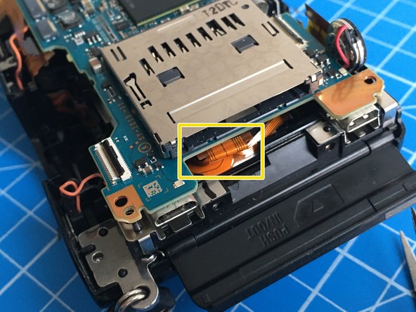
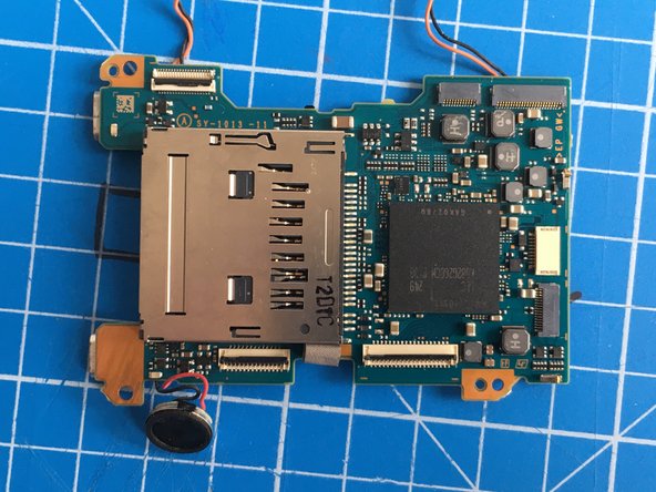
- The mainboard has 8 flat flex cables connected to it. 2 of them are hidden behind.
- One of the flex cables may have high voltage from the flash charge circuit, so be careful when touching around. The flex cable is at the back of the unit, in the area marked with red circle in the first photo.
- The bottom two flat flex cables have ZIF connectors with locking tabs. The rest are pressure fit, just pull them away gently using tweezers.
- Remove all the flat flex cables carefully by pulling them.
- When removing the mainboard, be careful not to rip the microphone and speaker cables off.
- Be careful with the high voltage flash circuitry as shown with the red circle in the first photo.
- Remove the flat flex cables from the sensor assembly by unlocking the lock tabs on ZIF connectors.
- Remove the plastic cage battery holder by wiggling it out from its place.
- Be careful about the high voltage flash charge circuitry, as shown in the last photo.
- Release the strap eyelet assembly by removing the silver self-tapping screw as marked in the first photo.
- Remove 5 silver self-tapping screws as marked.
- Remove the metal frame.
- Remove the lens mount, shutter and sensor assembly from the camera body.
- Remove 3 marked silver self-tapping screws to release the sensor assembly. Pay attention to the sensor adjustment shims. Do not misplace them.
- Do not touch the sensor surface. Keep it at a safe and clean location.
- Pay attention to the shim locations. Your camera may have different coloured and different number of shims.
- Remove 3 marked black self tapping screws to release the shutter assembly.
- Gently remove the thin metal shield around the shutter unit. Pay attention to the tiny tab engaging with the circuit board, as marked in the first photo.
- This step is the actual repair procedure for the shutter error.
- The error is caused by a weakened shutter return spring. Due to extensive use it doesn't have the power to close the shutter.
- Normally the motor opens the shutter curtain and engages the mechanism with a small neodymium magnet.
- When the electromagnet is activated, the neodymium magnet is disabled and the shutter curtain has to travel towards closing direction with the help of the return spring.
- However, when the return spring is not strong anymore, it cannot move the curtain.
- For repair, using a pair of tweezers, turn the spring adjustment wheel (the black round wheel with teeth, bottom one shown with red arrow) for 2-3 clicks towards the direction of green arrow. Compare the first and the last photo for the amount of rotation, it is only a tiny bit!
- This should do it.
- Re-assemble everything back in the same order of disassembly. Be careful when connecting the flat flex cables. It is very easy to damage them.
- Test the camera. It should work now, but in case the error persists, try moving the spring adjustment wheel for one or two clicks more.
- If it still doesn't work, you may need a new shutter assembly. There are plenty on sale, you can find it if you look for it.
- Good luck!