Acer K202HQL Monitor LCD Panel Replacement
ID: 157680
Description: Here is a Acer K202HQL monitor that had fallen....
Steps:
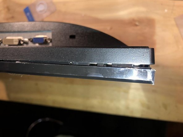
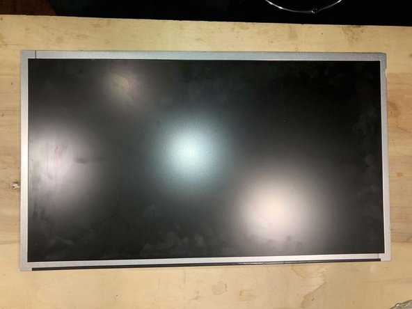
- Here is what the monitor shows after having fallen of a desk. Obviously broken LCD panel
- The monitor is a K202HQL with LCD backlight and made in 2020
- First we have to remove the stand. It is comprised of the foot (round plate) and the leg (between foot and monitor). Acer actually has a wing screw on the bottom of the foot. Simply flip up the wing to turn the screw to remove it.
- The leg is a bit more complicated. It locks in a tab
- Use a flat tip screwdriver to push the tab down
- Slide the leg out at the same time. Needs a bit of force to pull but comes out cleanly
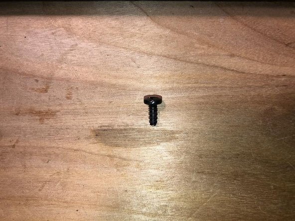
- Remove the one (1) Philips screw
- It's 3/8 inch long
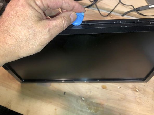
- Next use a plastic opening tool and insert between the front bezel and back section
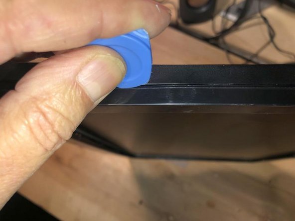
- Here the housing is not a press-fit, but there are tabs that hold it together. Slide the opening tool along the seam
- once you find the next tab, apply some downward pressure to release it.
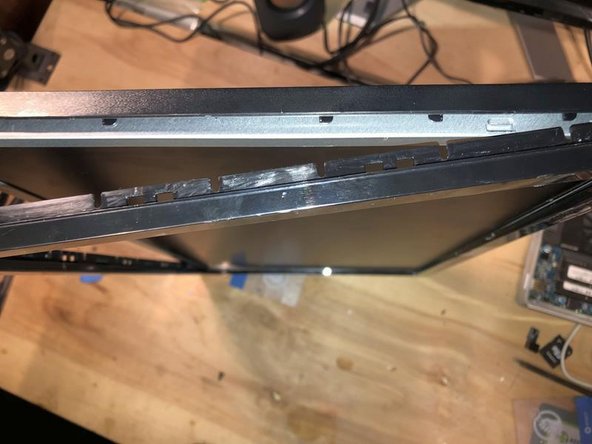
- Once released, the bezel will slowly fall away. Make sure it does not crack while it is trying to do this.
- Start that the the top and then the sides
- Finally the bottom
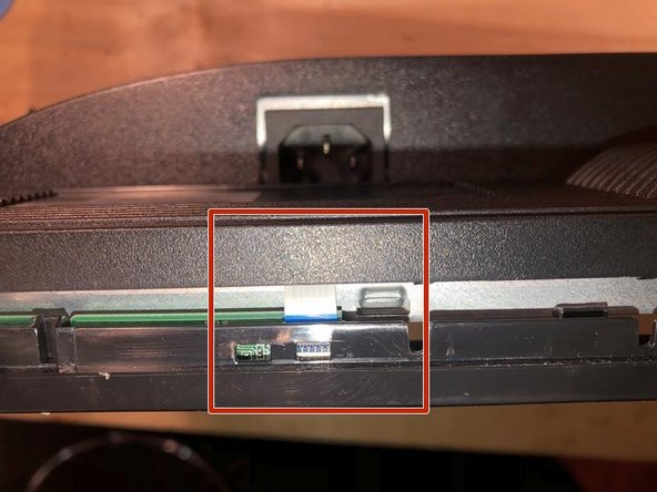
- Careful here, the ribbon cable from the button bar runs right across. Do not cut it accidentally with the opening tool
- Once all the tabs have been released, the back will simply come of the bezel
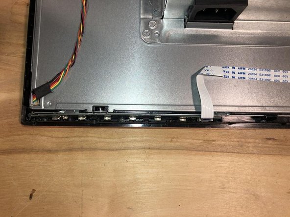
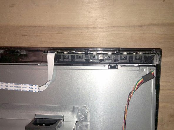
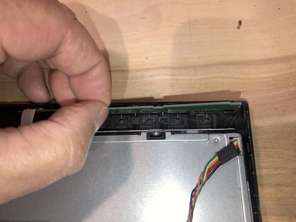
- Lay the monitor so you can access the cables. Here we see the button bar which is still attached to the bezel.
- It is clipped into the bezel by some tabs
- Slightly bend it inward to free it from the clips
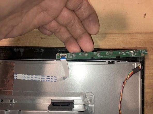
- Then slide it out
- and it is now free from the Bezel
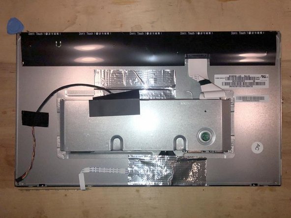
- Let's take a quick look around. This is the label which we will use to find a replacement LCD panel. It has the model as well as revision number on it.
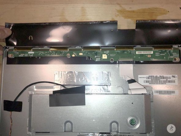
- Here is the complete cabling as well as something hiding under the "Do Not Touch" warning. Ha, lets touch!
- That is the LCD Driver board. It is adhered to the LCD panel via a special process. It is not (yet) replaceable by DIY'er means. This is not a T-Con board
- Here is the label just in case anybody looks and can find information on it. There is not much information on these boards.
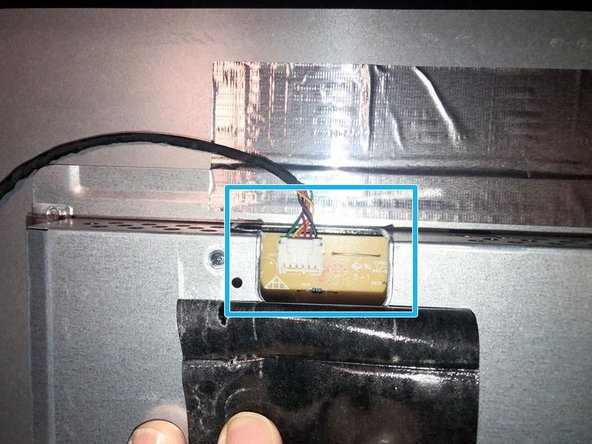
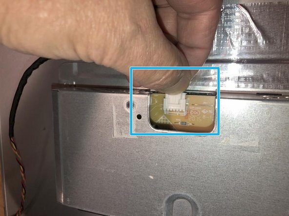
- First cable we are going to remove is the backlight cable.
- Pushing down on the center of the connection will lift the locking tab and the cable can be pulled out.
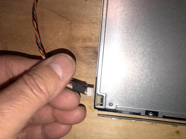
- Here is the other end of the backlight cable.
- This one just pulls straight up to remove
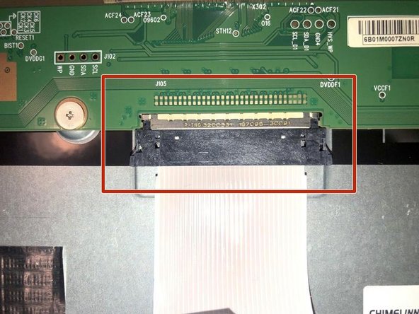
- Next is the LVDS connector
- To remove the LVDS connector simply squeeze the connector together to release the tabs and pull the connector out
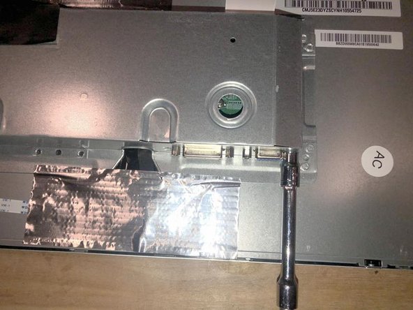
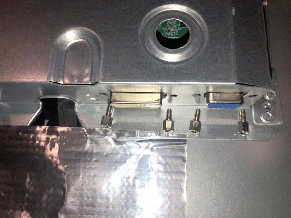
- Next remove Four (4) long hex screws with a 5mm nutdriver.
- Here are the 4 screws that have to be removed. 2 for the VGA port and 2 for the DVI port
- There are two strips of what feels like thick aluminum tape. Those are actually used as EMI shielding and will have to be transferred to the new LCD panel
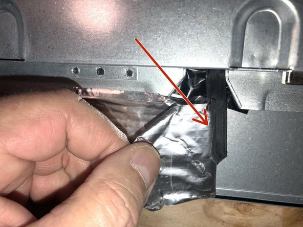
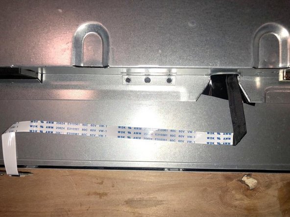
- Careful with the one on the bottom. The button bar flex cable in stuck to the panel with this tape.
- The flex cable is adhered to the panel with some light adhesive
- Now remove the aluminum stick tape from the top part. It adheres the main and power board
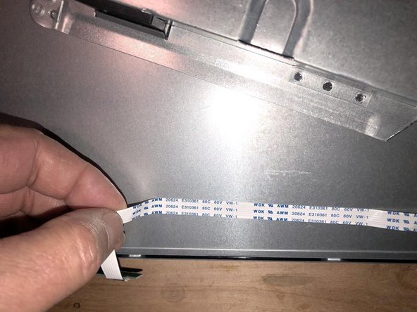
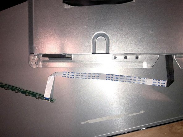
- Next, gently lift the button bar cable from the back of the display. Keep your fingers short to where you remove it so it does not tear
- The button bar cable will now be completely off and free.
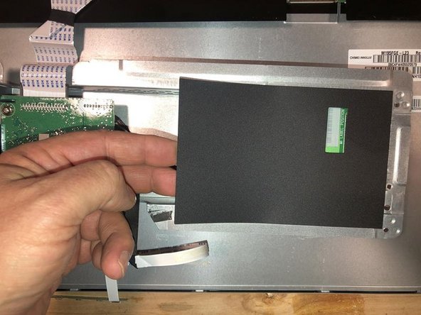
- You can now turn the assembly that holds the power board and the main board over or just remove it.
- Left is the main (video) board and right the power board. Just a quick removal of the insulator sheet (separate power board from metallic rear cover of the panel)
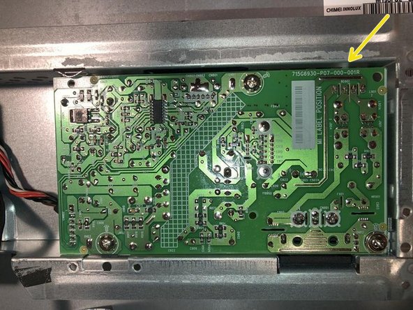
- Here is the power board. The part numbers for the boards are silk screened to the boards.
- Just a better view of the main (video) board in case somebody needs to find a replacement
- Finally with everything removed all that is left is the panel. Just like any other monitor or even TV. The LCD panel is the foundation that is used to mount everything else to it.