Asus ROG STRIX GL502V Motherboard Replacement
ID: 157714
Description:
Steps:
- Remove 10 screws.
- Note: front screws (blue) are 10mm long, central and rear (brown) are 12mm.
- With opening tool or pick go around the case starting from back corner.
- Lift cover and now you have access to most of the components.
- Disconnect battery connect by pulling it up.
- Remove 4 screws
- Lift battery up and out.
- Pull spring locks out.
- Lift module up and out of the connector.
- remove screw.
- pull up and right from the connector.
- Antenna (orange)
- Speakers (yellow)
- Power and miscellaneous LED (blue)
- Keyboard (green)
- Display (pink)
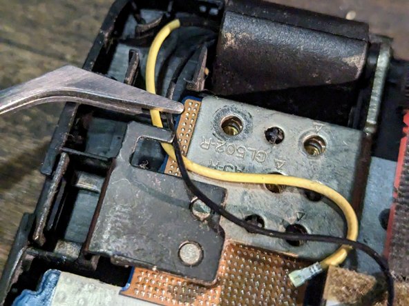
- Remove speaker connector by pulling it out.
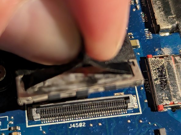
- Lift locking mechanism up
- Pull ribbon cable from connector
- Lift locking tab on each connector (3x)
- Pull each ribbon cable out
- Remove screw holding display cable
- Remove plastic shield over display cable
- Pull cable out of the clip
- Pull display connector straight up by the pull strap
- Carefully holding by metal part pull connector up.
- Repeat for second connector.
- Move connector out of the guide.
- Remove remaining hinges screws (5)
- Note: one screw was holding display cable.
- Lift left hinge up.
- Lift right hinge up.
- Remove two side motherboard screws (yellow marks)
- Remove 4 center screws (green marks)
- Note: side screws silver and slighter longer.
- NOTE: Headset connector is holding in the case.
- Lift motherboard from HDMI connector side and pull towards it.
- Remove radio module screw (red) and pull it out of connector.
- Disconnect fans connectors and remove 6x screws. Pull fans out.
- Remove 8 screws from heat sink and remove it.
- Note: heat sink use thermal paste on CPU and GPU - you will need to clean and use new before putting it together.