Brother DCP-J4120DW MFC-J4320DW MFC-J4420DW MFC-J4620DW J4625DW Printer no longer turns on
ID: 157768
Description: This problem often occurs with the Brother...
Steps:
- Disconnect the printer from the power supply, then open the cover under which the USB port is situated. There are corresponding recessed grips on the side surfaces of the printer.
- To remove the cover holder, pull out the sliding piece at the rear end (picture 2). The holder can then be pulled out upwards.
- Before we separate the cover from the printer, the two cable connections must be disconnected. To do this, remove the cover by lifting it on the right side.
- Now pull off the two cables (picture 2). If it is difficult, you can carefully use flat-nose pliers.
- The cable holder, which is rotatably attached to the cover, is lifted upwards and then the cover is pulled out to the rear.
- Once the cover is removed, you can see a total of 6 Phillips screws that must now be unscrewed.
- The cover can then be removed upwards.
- The metal module that contains the power board can be seen on the bottom of the printer on the right. In order to be able to pull this out, the plug in the first part (Figure 2) is removed and the wires are carefully pulled out of the holder, preferably with tweezers.
- The front left printer cover is removed by loosening the snap connection with a screwdriver in order to access the second screw connection of the power module and to unthread the cable.
- Thread the cable out of the brackets at the front.
- As shown in Figures 2 and 3, the two Phillips screws must be removed, however be careful not to lose them by accidentally dropping them into the depths of the printer.
- After derouting the cable and releasing the clamp connection by pressing on the metal bracket, the module can be pulled out downwards (Figure 1).
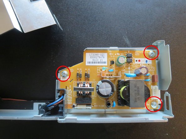
- Pull the cable off the circuit board. In order to reassembly everything correctly, note how the cable is routed through the metal housing.
- Unlatch and remove the metal cover by lifting the tab.
- Remove the grounding screw from the power plug and remove it with the cable from the holder (Figure 2). The two cable routing parts are only plugged onto the metal carrier. For the installation it is important how the cable is routed to the circuit board (image 3)
- Remove the screws on the circuit board. The new circuit board can then be installed.