Samsung Galaxy A510F, replacement of USB PCB, jack and buttons
ID: 157977
Description: Changing the USB port for this model is tricky....
Steps:
- Insert a SIM card eject tool, a SIM eject bit or a straightened paper clip into the hole on the SIM tray located at the left side of the phone.
- Press firmly to eject the tray.
- Remove the SIM card tray.
- When reinserting the cards, make sure to properly orient them in the tray.
- Before beginning this procedure, completely power off your phone.
- Prepare an iOpener and apply it to the back cover to soften the adhesive.
- The adhesive of the Samsung Galaxy A51 is very strong. You can use a hair dryer or a heat gun if you aren't able to open the device with the iOpener.
- Be careful not to overheat the phone—the AMOLED display and internal battery are both susceptible to heat damage.
- Insert the tip of an opening pick between the frame and the back cover at the bottom of the phone near the USB-C port.
- If you can't get between the back cover and midframe with your opening pick, you can use a suction handle or strong tape to pull up the back cover to create a gap.
- Slide the opening pick to the bottom right corner and leave it there.
- Insert a second opening pick and slide it from the bottom right corner to the bottom left corner to cut the adhesive.
- Leave the opening picks in place to prevent the adhesive from resealing.
- Insert a third opening pick under the bottom left corner of the back cover.
- If you have any trouble, apply more heat to further soften the adhesive. Follow the iOpener instructions to avoid overheating.
- Slide the opening pick along the left edge of the phone.
- Leave the opening pick in the top left corner to prevent the adhesive from resealing.
- Insert a fourth opening pick under the top left corner of the back cover near the camera.
- Slide the tip of the opening pick along the top edge of the phone to the right corner to cut the adhesive.
- Leave the opening pick in the top right corner to prevent the adhesive from resealing.
- With opening picks in all four corners, insert a fifth and final opening pick under the top right corner of the back cover.
- Slide the tip of the opening pick along the right edge of the phone to the bottom right corner to cut the remaining adhesive.
- Remove the back cover.
- After installing the back cover, apply strong, steady pressure to your phone for several minutes to help the adhesive form a good bond—a stack of heavy books works well.
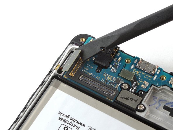
- Use the flat end of a spudger to pry up and disconnect the display flex cable on the bottom of the phone.
- Prepare an iOpener and apply it to the display for at least two minutes to loosen the adhesive beneath.
- You may need to reheat and reapply the iOpener several times to get the phone warm enough to cut the adhesive. Follow the iOpener instructions to avoid overheating.
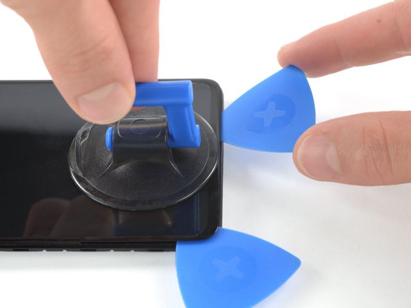
- Once the screen is warm to the touch, apply a suction cup to the upper edge of the phone.
- If the screen is cracked, the suction cup may not stick. Try lifting it with strong tape, or superglue the suction cup in place and allow it to cure so you can proceed.
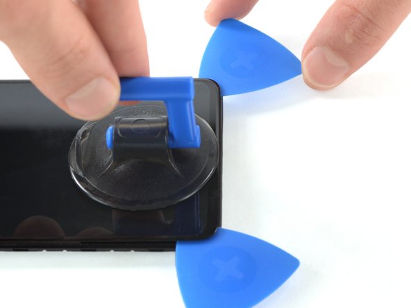
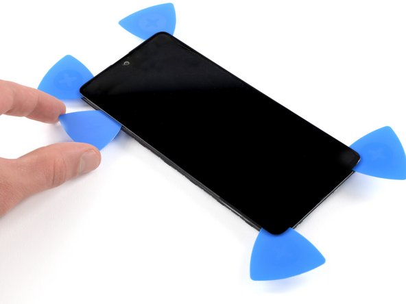
- Insert an opening pick in the gap and start to cut the adhesive by sliding it to the top right corner.
- Insert a second opening pick and slide it to the top left corner.
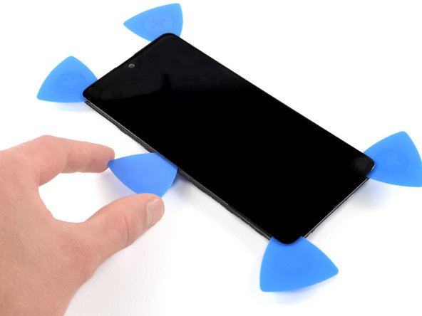
- Leave the opening picks in place to prevent the adhesive from resealing.
- Insert a third opening pick and slide it along the left edge to cut the adhesive.
- Leave the opening pick in the bottom left corner to prevent the adhesive from resealing.
- Insert a fourth opening pick and slide it from the bottom left corner to the bottom right corner.
- Leave the opening pick in its place to prevent the adhesive from resealing.
- Insert a fifth opening pick and slide it along the left edge of the phone to cut the remaining adhesive.
- Reapply a heated iOpener to the screen to loosen the adhesive underneath.
- As you wait, take note of the rectangular-shaped adhesive placed underneath the screen.
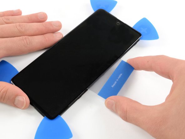
- Insert a plastic card on the left edge into the gap between display and the phone assembly.
- Press the plastic card in and slide it back and forth until you cut through the entire adhesive.
- Once you are sure you cut through the adhesive, remove the four opening picks from the corners.
- Do not remove the screen completely yet. The display cable is still threaded through the frame.
- Carefully thread the display cable through the frame.
- Remove the screen.
- Disconnect the antenna connector at the lower right
- Use a spudger to disconnect the main board connector from the rear side of the PCB.
- Use the flat side of the spudger to unglue the microphone from its compartment.
- Be careful with the flex cable, as it is quite thin.
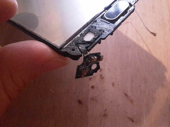
- Peel off the PCB from its compartment and lift it to the other side without pulling.
- Proceed element by element, trying not to break the flex parts. Here you’ll notice I broke the flex surrounding the jack port.
- Take care not to damage/disconnect the two flex cables connected to the buttons at each end of the PCB (circled in red on the photo)
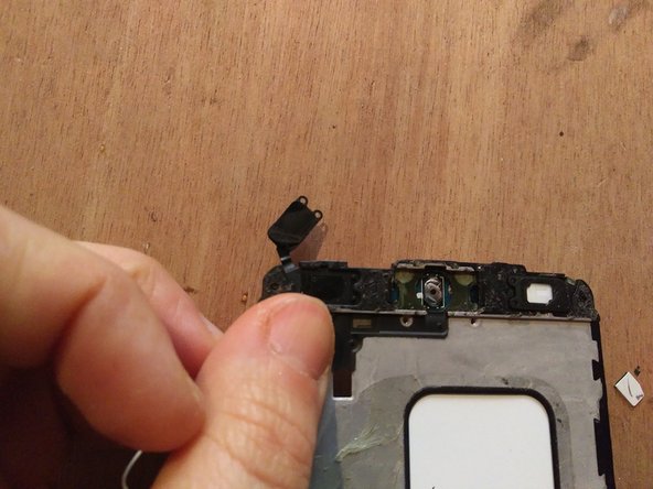
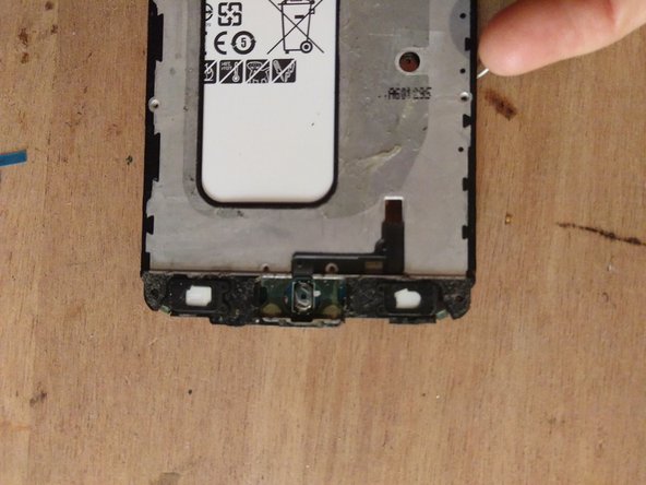
- Remove or raise the glass on the other side of the phone.
- Peel off the two button connectors.
- This is a view of the entire replacement board.
- Note the flex parts circled in yellow on the photo: those are the most fragile parts of the PCB.
- Place the new USB board in its casing
- Plug the connector to the main board, below said board
- Remove stickers from glued parts on new board
- Remove the previous while filtering sticker under the buttons
- Glue both backlight elements into their casing
- Plug back the antenna connector
- At this point, there are 17 screws to be reassembled at the back of the phone
- Glue screen and back cover back in place