Sony a7 Shutter Replacement / Complete Disassembly
ID: 158234
Description:
Steps:
- Flip the camera upside down, and observe where the battery door and switch are located on the camera.
- This replacement guide is using a cardboard and tape placeholder to simulate the battery, battery door, and switch.
- Slide the switch over to the right side to open the battery door.
- This replacement guide is using a cardboard and tape placeholder to simulate the battery, battery door, and switch.
- Depress the blue lever to allow the battery to pop out slightly.
- This replacement guide is using a cardboard and tape placeholder to simulate the battery, battery door, and switch.
- Remove the battery from the camera.
- Make sure to hold onto the battery firmly when removing it from the camera, as it could slide out and fall.
- This replacement guide is using a cardboard and tape placeholder to simulate the battery, battery door, and switch.
- Remove the eyepiece cover by removing the four M1.5x4mm screws with a PH00 Phillips screwdriver.
- Remove the M1.5x4mm screw that retains the adjustment wheel with a PH00 Phillips screwdriver.
- Remove the six M1.5x4mm screws with a PH00 Phillips screwdriver.
- Remove one M1.5x4mm screw with a PH00 Phillips screwdriver.
- Remove the four M 1.5x2mm screws.
- Once the screws have been removed, unsnap and lift the rear plastic cover off of the camera.
- Using the blunt tweezers, remove the blue ribbon cable.
- For additional guidance and tips on how to properly attach and detach connector cables, please reference iFixit's guide to connector cables here.
- Place the tweezers on the side of the circuit board and lift it from underneath so as to free it from the three retaining tabs.
- Remove four M1.5x4mm screws using a PH00 Phillips screwdriver.
- Lift the metal plate and LCD screen away from the camera body.
- Detach the amber ribbon cable from the motherboard.
- For additional guidance and tips on how to properly attach and detach connector cables, please reference iFixit's guide to connector cables here.
- Peel off the small adhesive tape located on the top right side of the motherboard.
- Remove the exposed ribbon cable by using the iFixit opening tools
- For additional guidance and tips on how to properly attach and detach connector cables, please reference iFixit's guide to connector cables here.
- Peel off the large black protective adhesive from the motherboard.
- Remove the four visible ribbon cables by using the spudger.
- Removing the ribbon cables will require lifting a lever located on the connecter in order to pull out the cable.
- For additional guidance and tips on how to properly attach and detach connector cables, please reference iFixit's guide to connector cables here.
- Remove the one U.FL plug by using the spudger.
- Using the spudger, remove the four remaining ribbon cables.
- These ribbon cables do not have the requirement to lift a lever on the connector as specified in previous steps.
- For additional guidance and tips on how to properly attach and detach connector cables, please reference iFixit's guide to connector cables here.
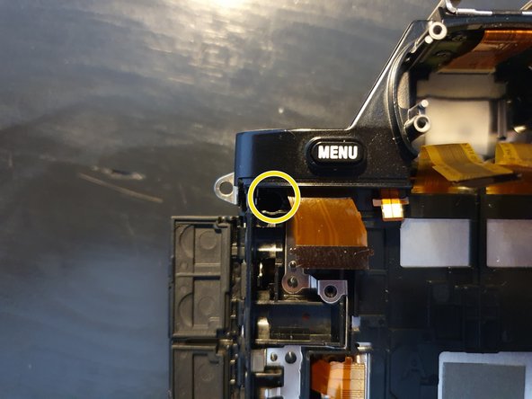
- Remove one M1.5x2mm screw with a PH00 Phillips screwdriver.
- Remove one coarse threaded 5mm screw with a PH00 Phillips screwdriver.
- Lift the motherboard from the camera body.
- It helps to pick up the right side of the board first, and then work sequentially down the board. Be sure to gently ease the motherboard from its clips down the remainder of the side.
- Exercise extreme caution when removing the motherboard as it can be fragile, and damage to it could mean the camera will become unrecoverable.
- Remove the two visible ribbon cables by using the forceps.
- Removing the ribbon cables will require lifting a lever located on the connecter in order to pull out the cable.
- For additional guidance and tips on how to properly attach and detach connector cables, please reference iFixit's guide to connector cables here.
- Gently pull the viewfinder out ouf the housing
- Remove the two M 1.5x2mm screws.
- Remove the M1.5x4mm screw.
- Remove the two M1.5x4mm screws.
- Pull of the grip to the front
- Remove the M1.5x4mm screw.
- Pull the grip of to the front
- Grab the top part on the sides and gently remove it to the top direction.
- Remove the two M1.5x4mm self tapping and the M1.5x4mm screw.
- Pull of the small metal plate.
- Remove the cable from the ribbon connection.
- Remove the adapter cable.
- Remove the three M1.5x4mm self tapping screws.
- Remove the M1.5x4mm screw.
- Gently pull of the back cover. Pay attetion to the ribbon cables.
- Remove the tripod thread.
- Remove the M1.5x2mm screw.
- Remove the connector on the side of the camera.
- Pull out the battery housing to the back.
- Remove the two M1.5x5mm screws
- Remove the copper plate from by lifting it from the right side.
- Remove the M1.5x5mm screw.
- Gently remove the sensor board.
- Remove the M1.5x5mm self tapping screw.
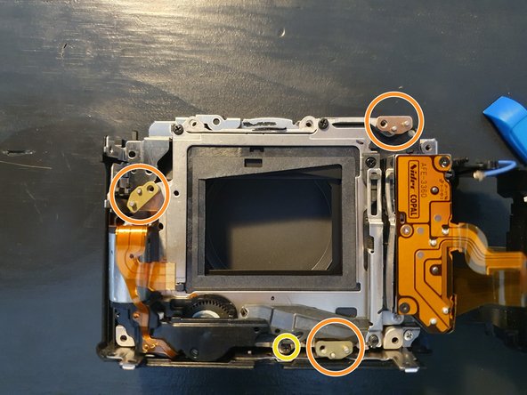
- Remove the four small support plates.
- Remove the front cover of the camera.
- Remove the three M1.5x4mm screws.
- Lift of the shutter assembly.
- Remove the special screw on the backside of the shutter.
- Remove the shutter curtain from the shutter drive.
- Done :)