FIRST FA-5367-1 Toaster: Disassembly and Repair of the Toast Holder - Doesn't Rise and Get's Stuck
ID: 158546
Description:
Steps:
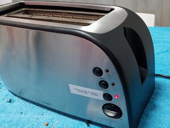
- Preventative maintenance of a slice toaster FA-5367-1. This article explains how to fix the intended toaster but can also apply to toasters that have have similar design and operation.
- In this instance, the issue is that one of the support guides for the bread is bent on both sides, causing it to not slide smoothly on the rail and get stuck in the middle while moving.
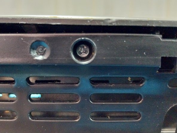
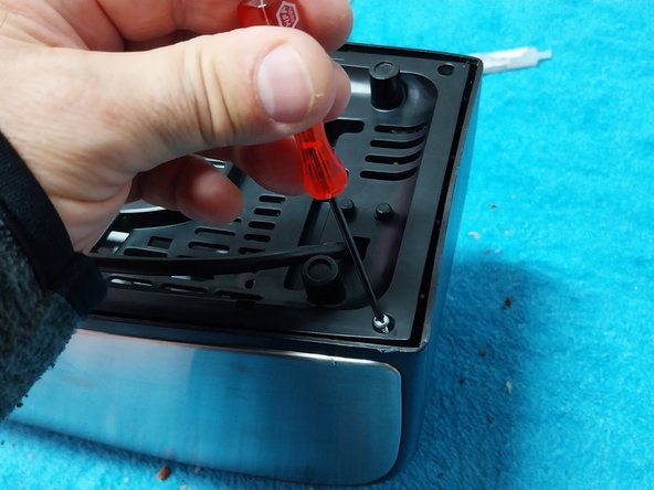
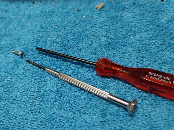
- This model is more complicated to repair without tools. It uses 6 security screws or 3-point screws which can be difficult to find in store. Fortunately, you can find these screwdrivers on the iFixit website or internet.
- As a last resort, you can try using a thin flathead screwdriver.
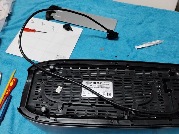
- Safety Measures Before Starting Disassembly Before starting the disassembly process, disconnect the machine by unplugging it.
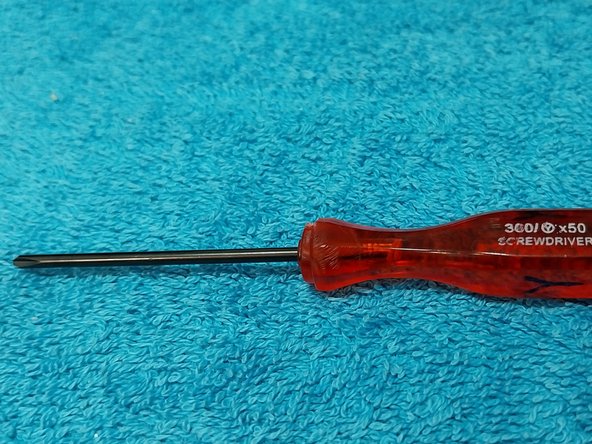
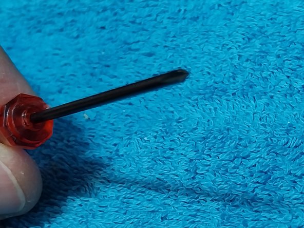
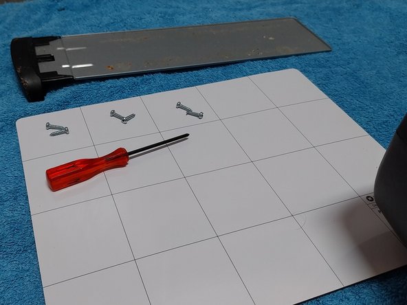
- Required Screwdriver: Tri-point Y00 Screwdriver
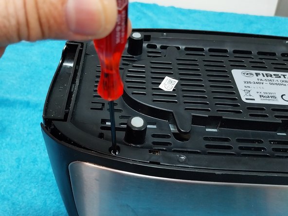
- Remove the 6 screws and organize them on the magnetic mat. Check that all the screws are the same and keep them organized in case other screws of different sizes appear later.
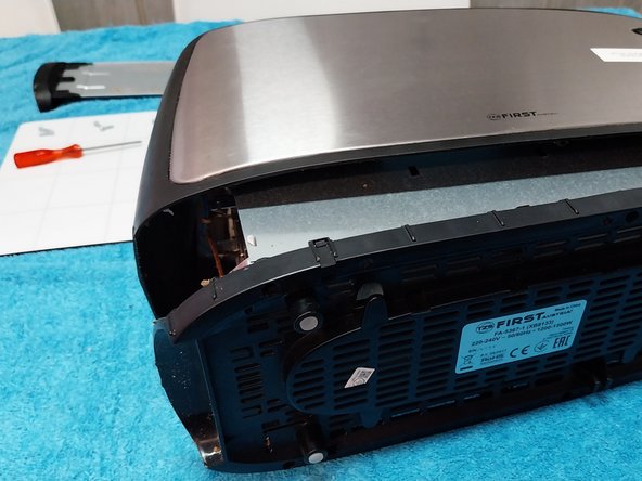
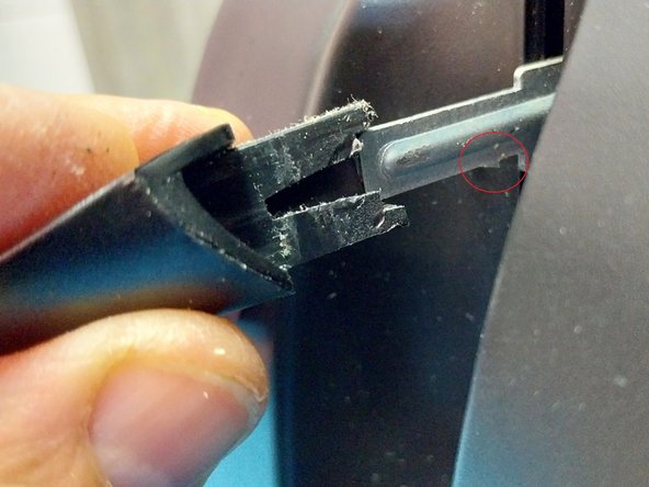
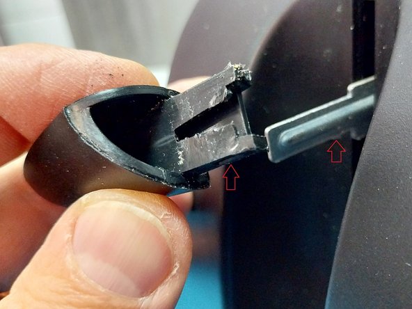
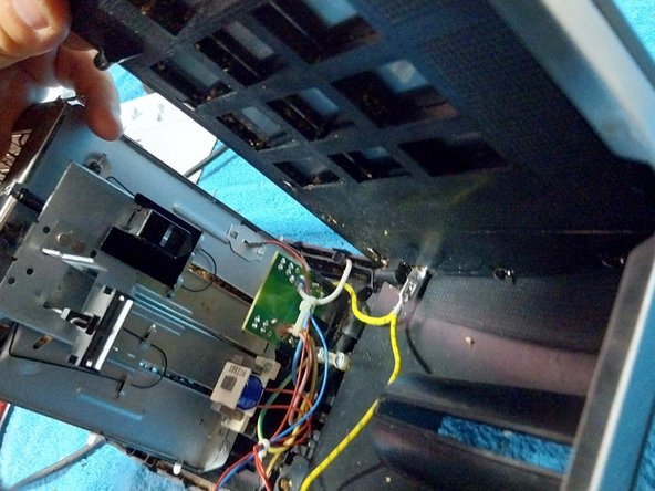
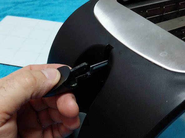
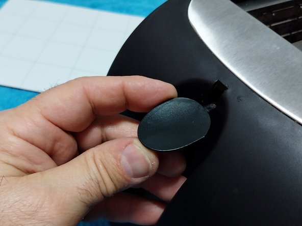
- Extraction of the power button: Every toaster has a tooth-like clip at the bottom. You need to carefully remove it without damaging the plastic.
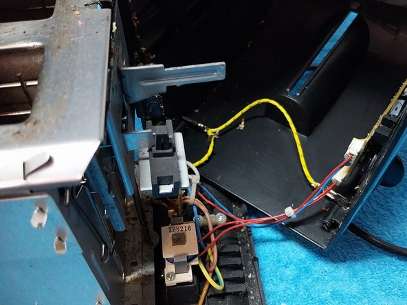
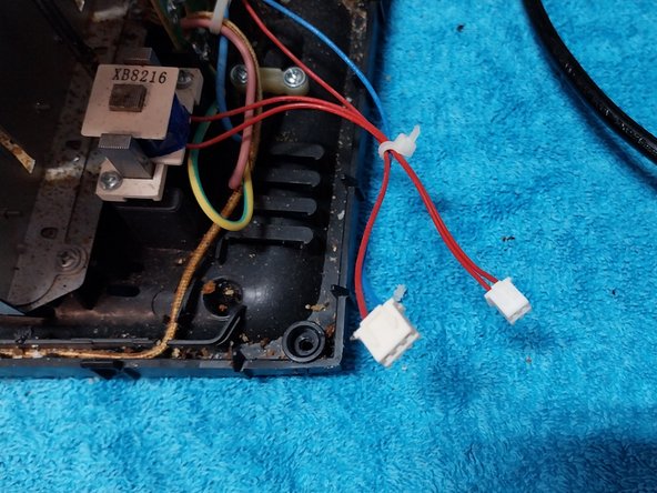
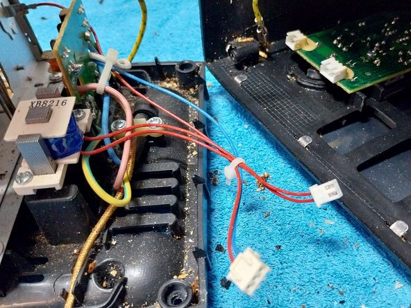
- Lift the cover up and disconnect the two connectors from the electronic board. In this model, they are different. Mark the position of both pieces so that you know how to insert them back later.
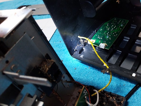
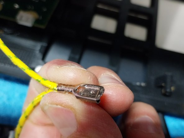
- After that, disconnect the faston terminal.
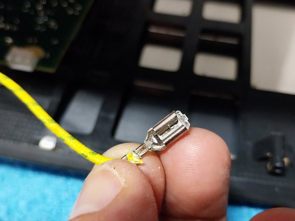
- The faston terminal is commonly used in many appliances like toasters and microwaves; it has a central tab that acts as a “safety lock” or “anti-vibration system.” Without the press of the tab with the tip of the screwdriver, it is impossible to remove the connector.
- Press the center tab and see that it movies from the side. At the same time, extract the terminal.
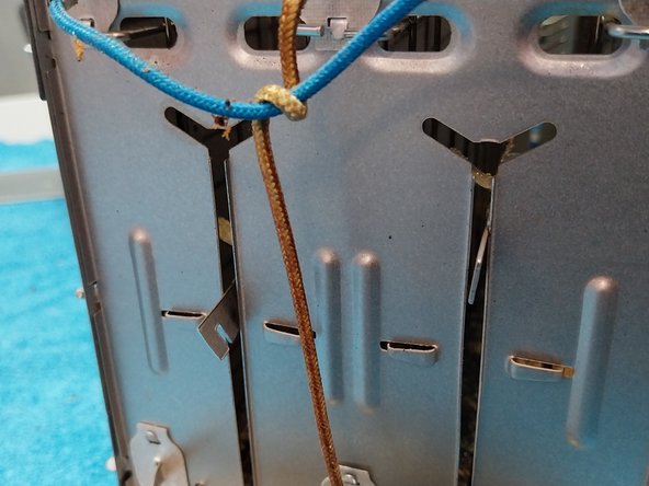
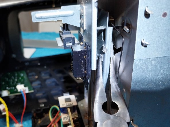
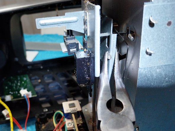
- Issue View: The left guide is bent, causing it to get stuck during movement. Straighten the guide by using a pair of flat-nose pliers, working on both the outside and the inside.
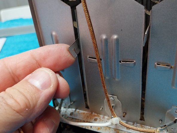
- On the side where the L-shaped toaster support is located, use the pliers to reinforce it as it likely deformed.
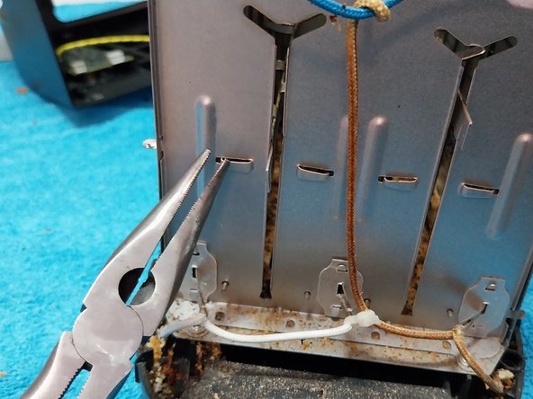
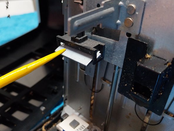
- Since the toaster is already open, perform a preventive maintenance and clean each of the three metal plates of the electromagnet that secures support at the bottom while the appliance is heating. These plates collect grease and breadcrumbs, which reduces magnetic adhesion when it should be activated.
- Continue to clean the top metal plate, which is the movable part.
- Photo Of Movable Metal Plate: This shows it closing the three parts of the “E” on the electromagnet.
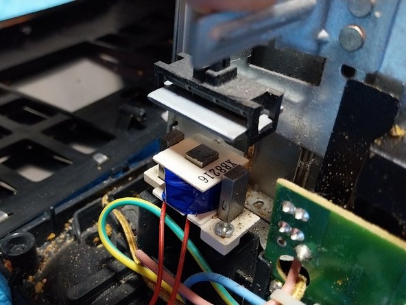
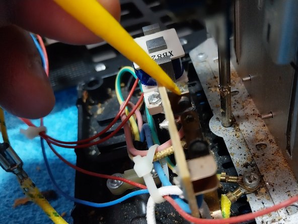
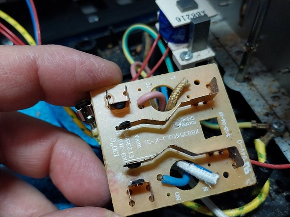
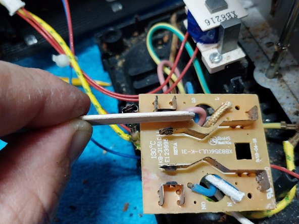
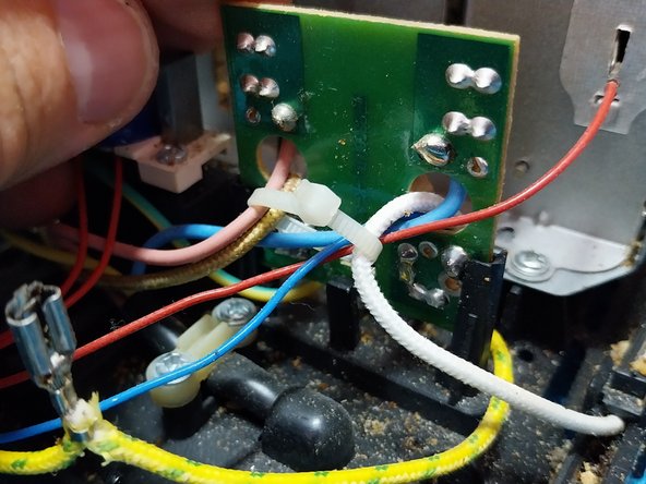
- This next step is to clean the clothe metal contacts “O points” of the power input. During operations, these metal contacts generate sparks which cause them to degrade, worsening the electrical connection until they eventually fail contact.
- As seen in the photo, they appear blackened and scorched.
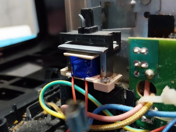
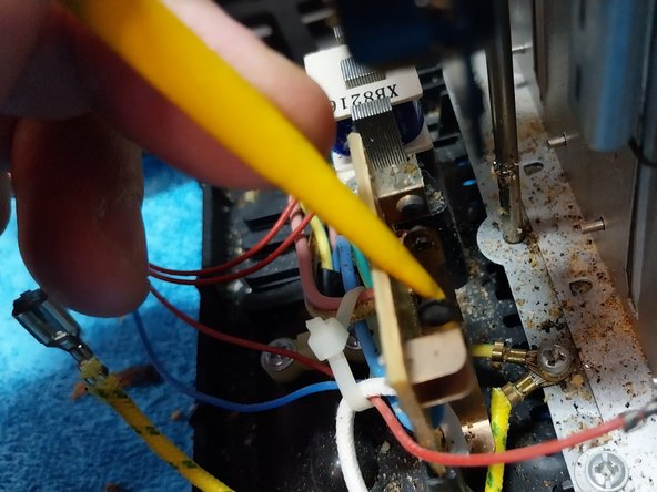
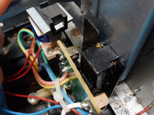
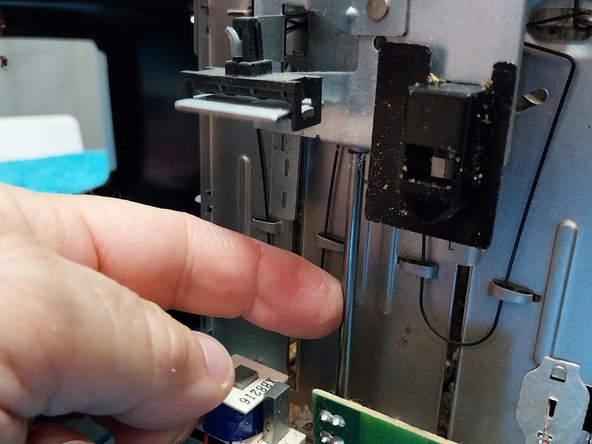
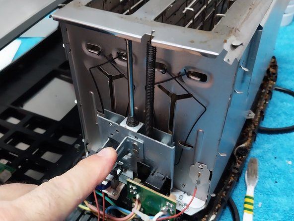
- Before proceeding with the disassembly, check the movement and locking mechanism of the plastic part that moves. This will help ensure the correct position of the electronic support board when you reassemble.
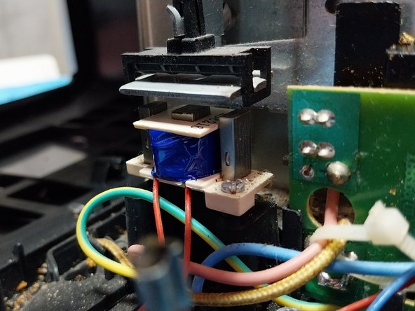
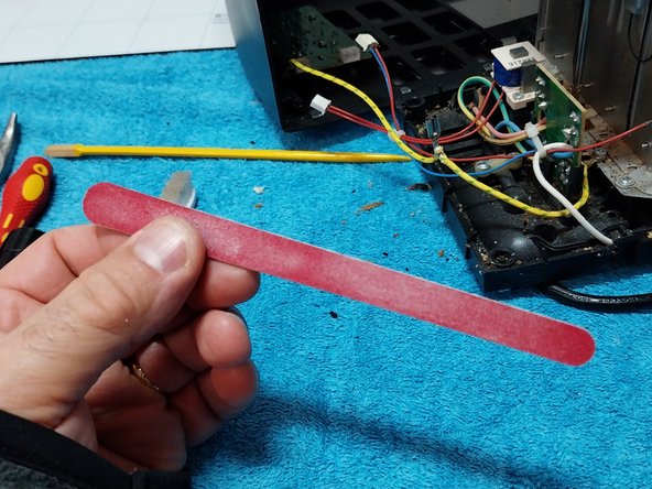
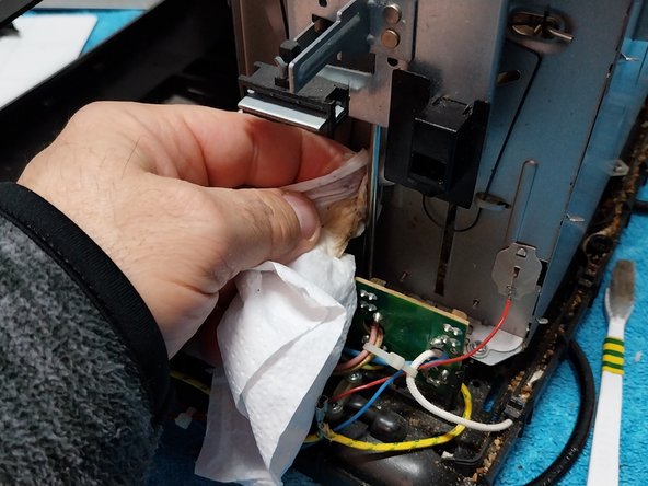
- Use a cosmetic nail file to clean the contacts with precision and ease. It is recommended to remove the electronic board to clean more comfortably. Once the contacts are cleaned, use a brush to remove any debris.
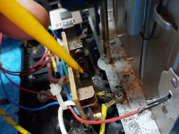
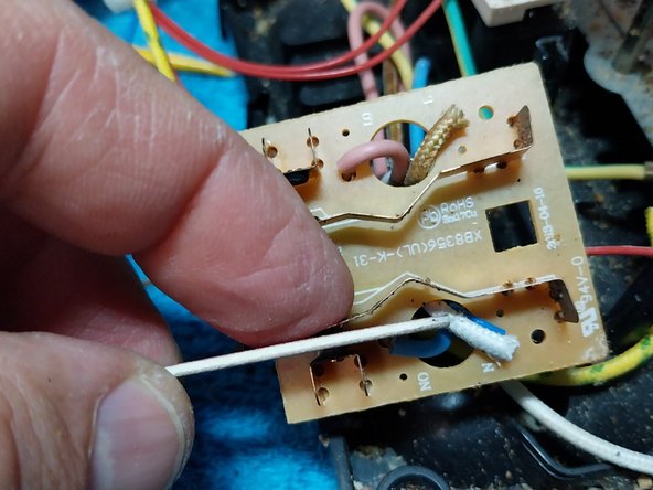
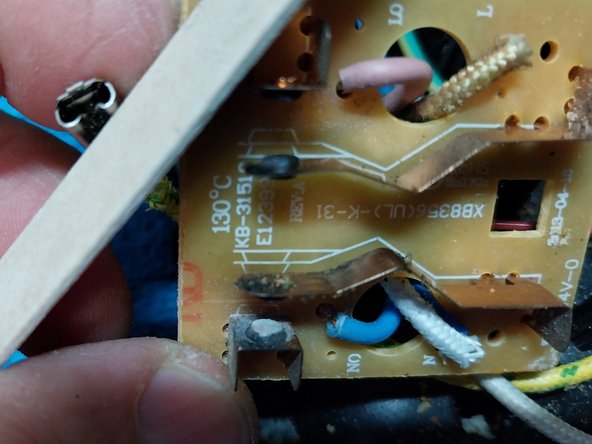
- This photo shows a detailed view of how to clean two pairs on contacts. It's recommended to press the contact together with your finger to brush or file the two terminals of the contacts at the same time using the same angle.
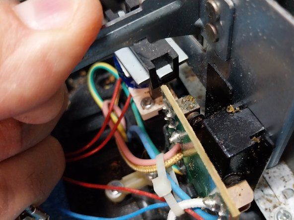
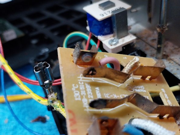
- This photo shows the terminals after being cleaned. It is not necessary for them to be completely shiny, removing the buildup is sufficient. Once cleaned, use a brush to remove any loose debris.
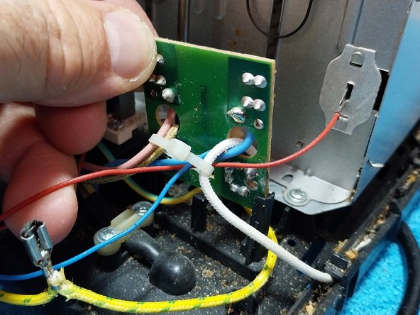
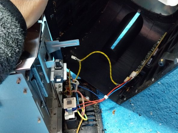
- Reposition the electronic board in its place, securing it with a plastic latch at the bottom. Check that the cables are not strained or rubbing against the yellow/green ground cable.
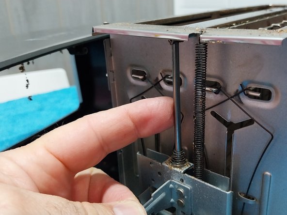
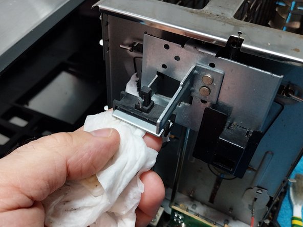
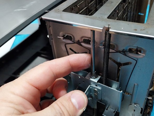
- Now it is time to address the stainless-steel guide or tube where it slides from the carriage. Over time, this tube accumulates dirt and grease, which prevents the moving part (carriage) from sliding smoothly. These buildups cause the machine to malfunction.
- Clean both the top and bottom of the moving carriage with a dampened cloth and alcohol.
- Clean the rectangular sheet metal piece that covers the electromagnet.
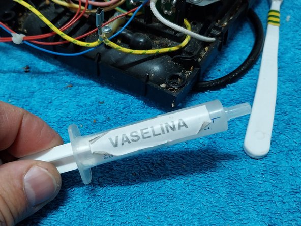
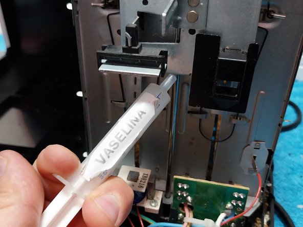
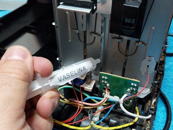
- Lubricate the stainless steel rod with Vaseline or light grease.
- Lubricate the entire surface of the stainless steel rod or guide using your finger.
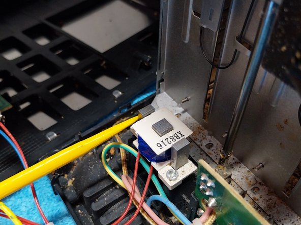
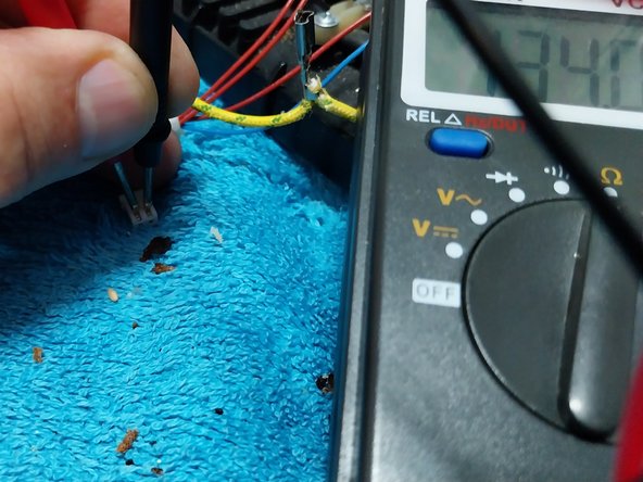
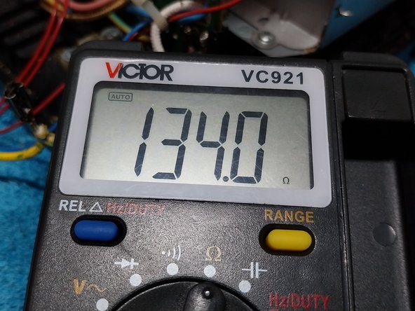
- This next step is not necessary, it's only for informational purposes: Since it is disassembled, measure the value of the electromagnet coil so we have an idea of its original value in case it fails in the future.
- Reverse assembly process, We reconnect the two connectors to their respective mates on the PCB and reconnect the ground wire to the housing.
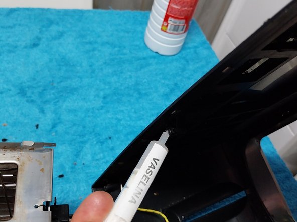
- To prevent the screws from damaging the plastic case when replaced and make it easier to disassemble the device in the future, apply Vaseline to each of the six 'stems'.
- Screw in the six screws with a triwing screwdriver. Another useful tip if you have screws of the same size, you can replace the specialized screws with standard ones.
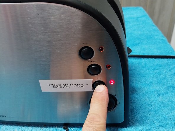
- Replace the selector knob.
- Device repaired and, with a little preventive maintenance done, it's time to enjoy it.
- Explanatory video of the maintenance performed.