LG WM3050CW Drain Pump Motor Replacement
ID: 158757
Description: Use this guide to replace the drain pump motor...
Steps:
- Before you begin your repair, perform the following:
- Turn off the main water supply
- Unplug your washer
- Disconnect all water connections at the rear of your washer
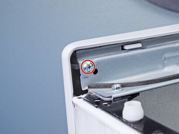
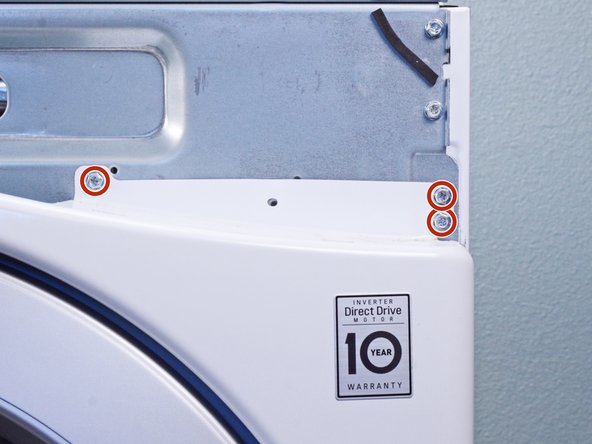
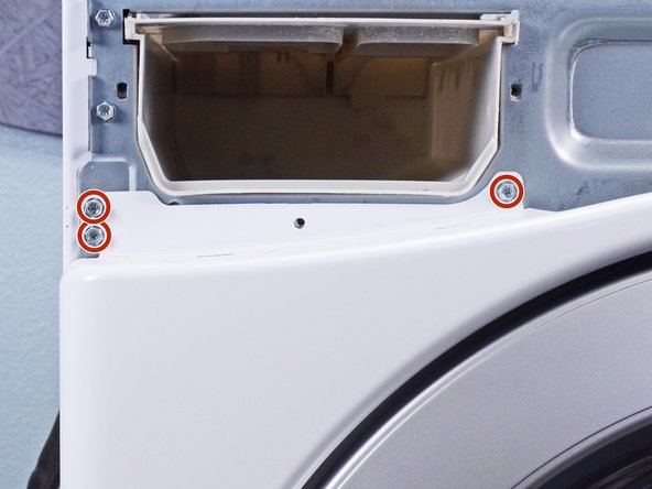
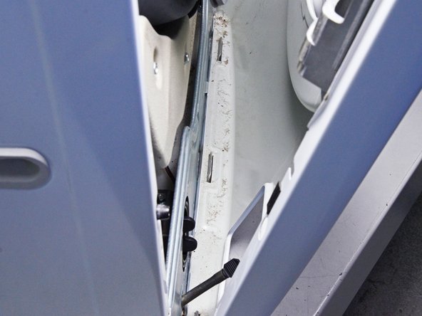
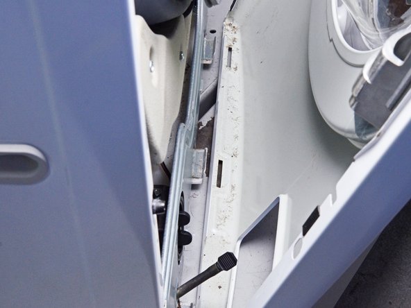
- Use a Phillips driver to remove the two bottom 16.5 mm-long screws securing the top panel brackets.
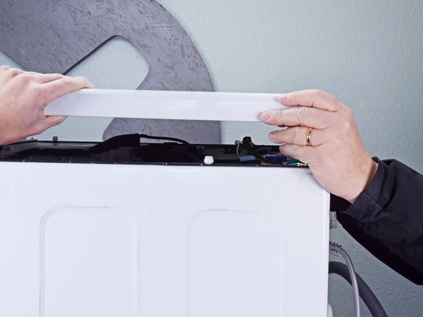
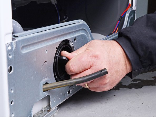
- Slide the top panel 1-2 inches towards the rear of the device to disconnect its clips.
- Tilt the top panel upward to completely disconnect it from the chassis.
- Remove the top panel.
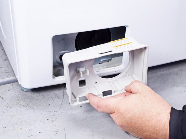
- Pull the detergent drawer away from the chassis as far as it will go.
- Press down on the "Push" button to disengage the clips securing the detergent drawer.
- Pull the drawer out of its slot on the chassis and remove it.
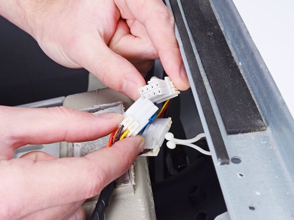
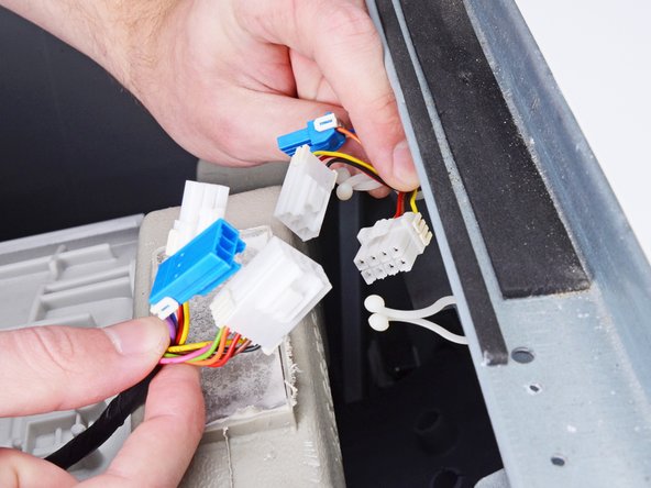
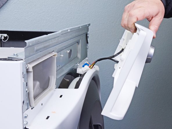
- Disconnect the three harness connectors for the control panel.
- Always grip cables by their connectors and not the wires themselves.
- Use a Phillips driver to remove the 16.4 mm-long screw securing the control panel.
- Use a Phillips driver to remove the two 26.3 mm‑long screws securing the detergent dispenser.
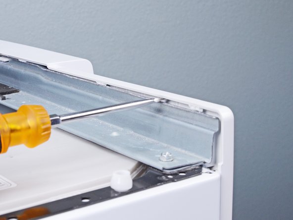
- Insert a flathead screwdriver between the chassis and the top left corner of the control panel.
- Twist the screwdriver to release the clips securing the control panel.
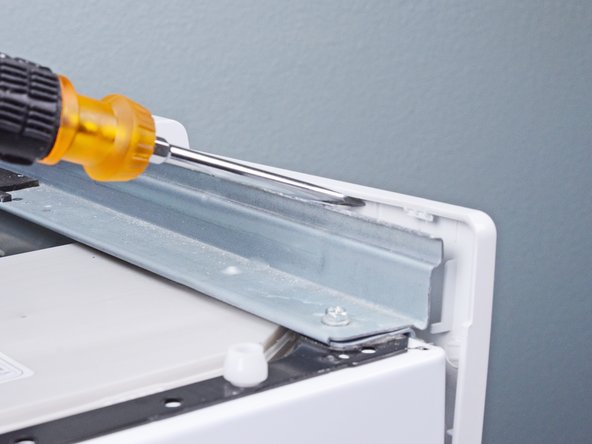
- Repeat this procedure for the remaining clips along the control panel.
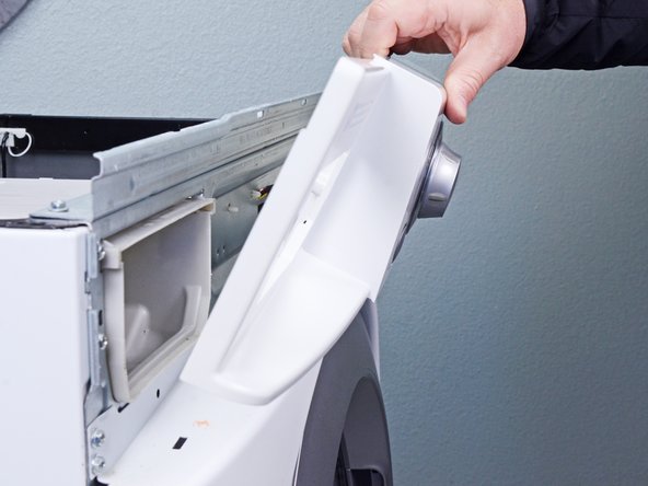
- Lift the control panel upward to completely separate it from the chassis.
- Pull the control panel away from the chassis, making sure to thread the cables through its slot in the chassis.
- Remove the control panel.
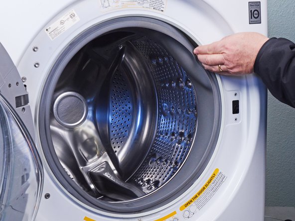
- Open the front door completely.
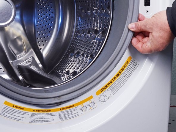
- Use needle nose pliers to grip the spring end of the metal ring at the bottom of the rubber boot.
- Pull the ring away from the chassis to separate it from the boot.
- Use your hand to completely pull the ring off the boot.
- During reassembly, perform the following:
- Insert one end of the ring into its groove along the boot's perimeter.
- Use pliers to slowly stretch the ring around the boot's perimeter until it's completely nested in its groove.
- This procedure will take significant force.
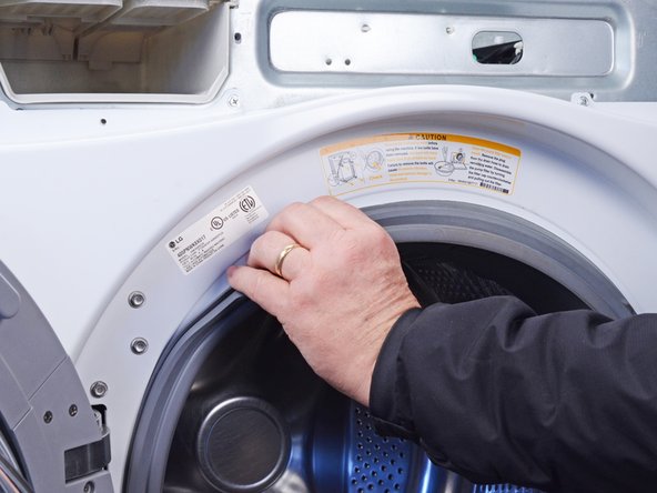
- Use your fingers to pull the boot off its lip on the front panel.
- Work your fingers around the boot until its completely separated from the panel.
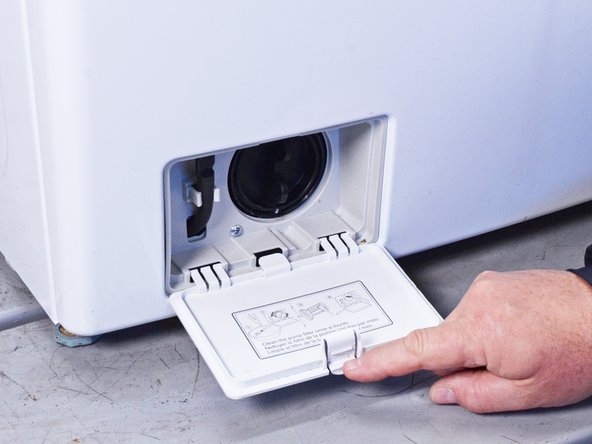
- Open the filter panel at the bottom left of the front panel.
- Twist the filter panel upward to unclip it from the front panel.
- Use a Phillips driver to remove the two 12.8 mm‑long screws securing the filter trim.
- Pull the filter trim straight off the front panel to remove it.
- Use a Phillips driver to remove the 12.8 mm-long screw securing the lower front panel.
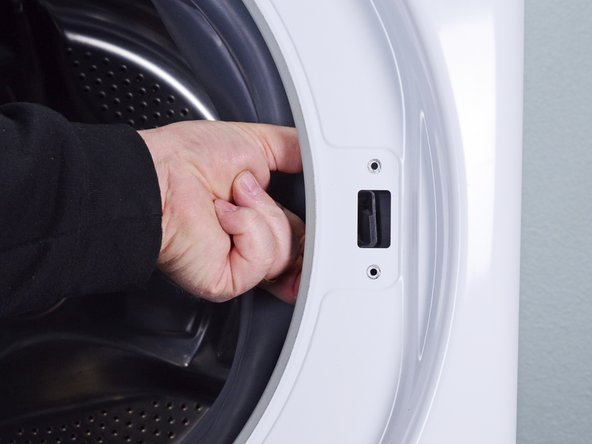
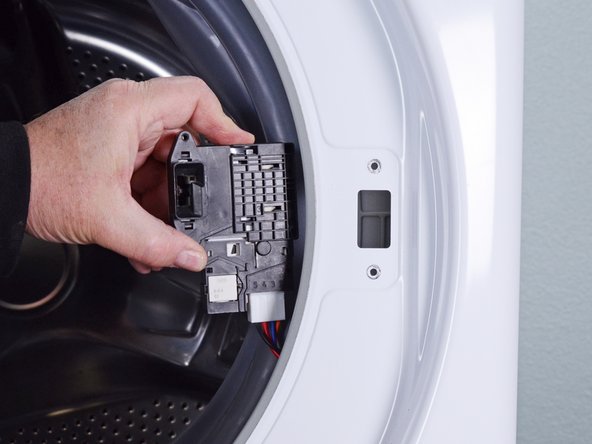
- Use a Phillips driver to remove the two 16 mm‑long screws securing the door latch.
- Pull the door latch through its slot in the chassis and let it hang on its wire.
- Hold the front panel against the chassis while performing this step to prevent it from falling.
- Use a Phillips driver, or a 7 mm nut driver, to remove the six 15 mm‑long screws securing the front panel.
- Lift the front panel upward to separate it from its clips on the bottom of the chassis.
- Pull the front panel away from the chassis to completely separate the front panel.
- Remove the front panel.
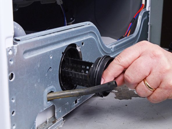
- Twist the pump filter handle counterclockwise to separate it from the pump assembly.
- Pull the filter straight out of the pump block assembly to remove it.
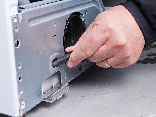
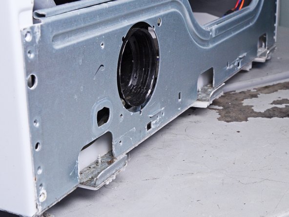
- Push the drain hose through its hole in the chassis until it's completely inside the device.
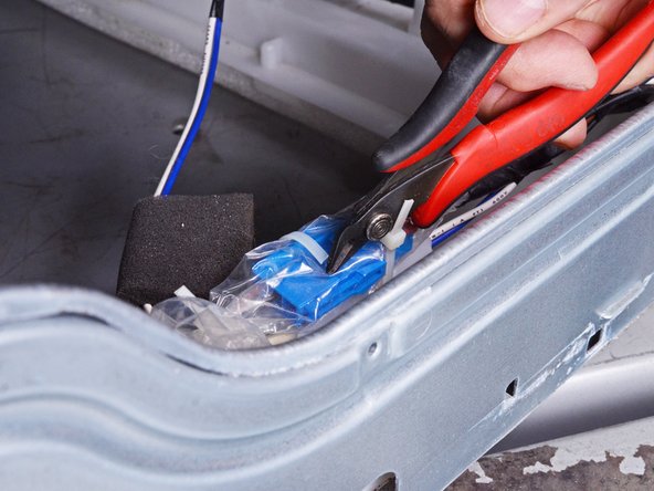
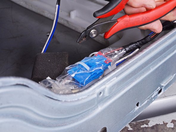
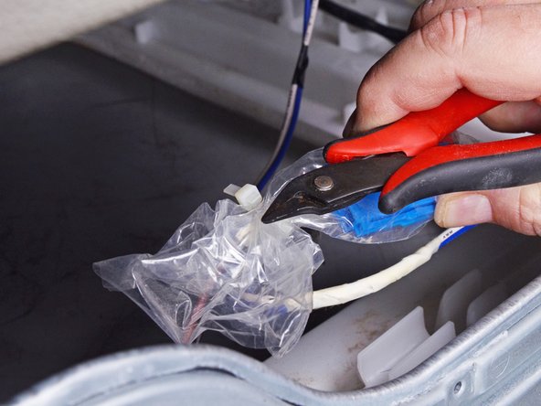
- Use diagonal cutters, or scissors, to remove the cable ties securing the plastic wrap to the pump assembly cables.
- Repeat the previous step for any cable ties bundling the pump assembly cables.
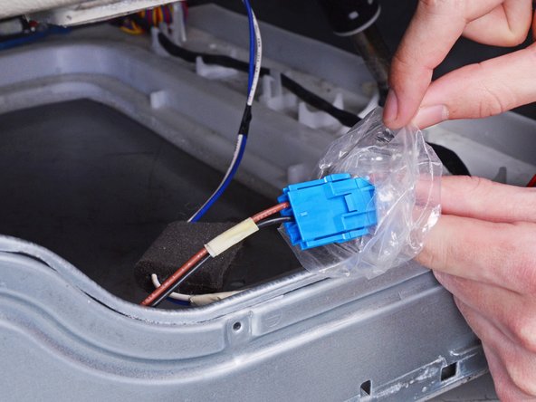
- Fold the plastic wrap away from the cables, enough to expose the connectors.
- During reassembly, replace the cable ties to ensure a water-tight fit for the plastic wrap.
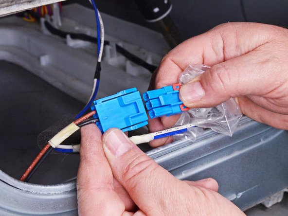
- Disconnect the connector attached to the pump cable.
- Always grip cables by their connectors and not the wires themselves.
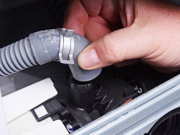
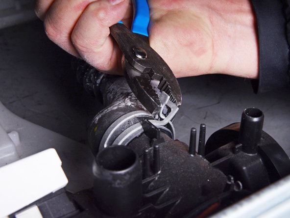
- Use slip joint pliers to pinch the pump discharge hose clamp and slide it up the hose away from the pump assembly.
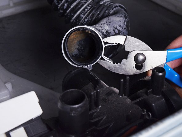
- Use slip joint pliers to rotate the pump discharge hose back and forth around its connection and loosen it.
- Pull the pump discharge hose straight off its connection on the assembly.
- Repeat the last two steps for the tub-to-pump hose.
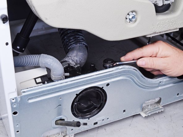
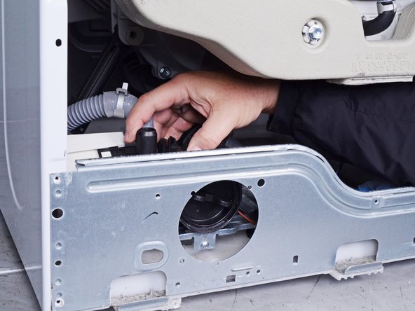
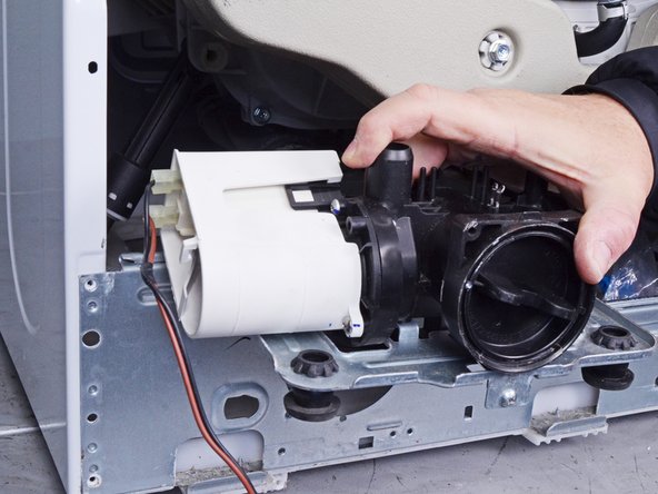
- Use a 3/8 inch socket wrench to remove the three 46.1 mm-long screws securing the pump assembly.
- Lift the pump assembly out of its location in the frame to remove it.
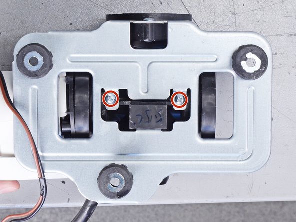
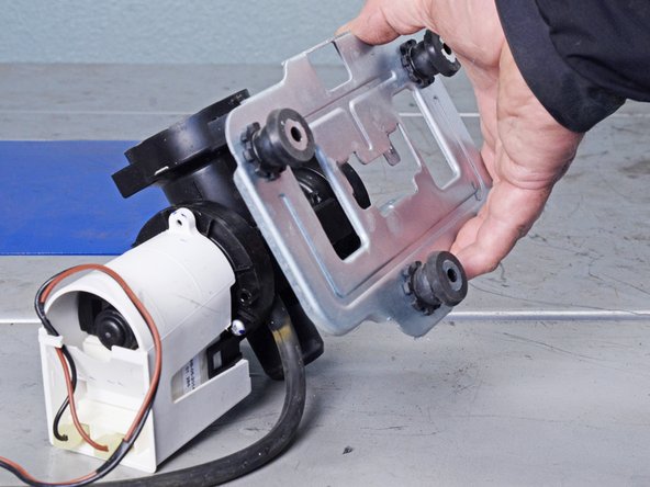
- Use a Phillips driver to remove the three 14.4 mm‑long screws securing the pump body.
- Pull the pump body straight off the pump to remove it.
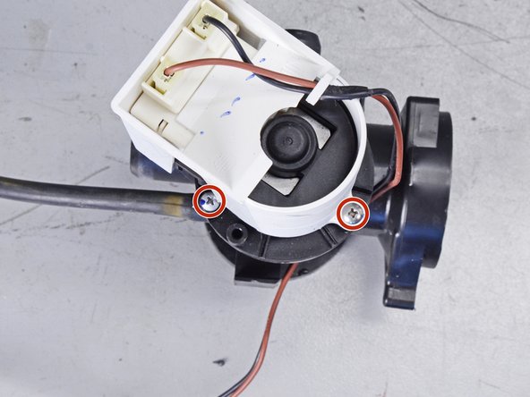
- To avoid confusion, note the locations of the motor screws.
- Use a Phillips driver to remove the three 21.6 mm‑long screws securing the pump motor.
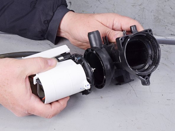
- Pull the pump motor straight off the pump to remove it.
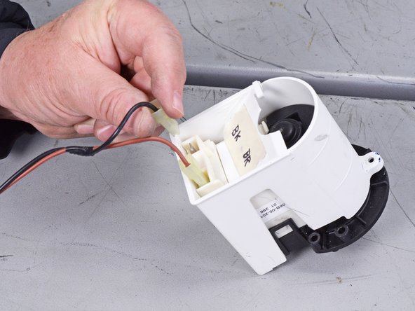
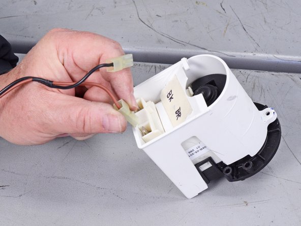
- To prevent confusion, label each spade connector with its corresponding cable color.
- Disconnect the two spade connectors attached to the pump motor.
- Always grip cables by their connectors and not the wires themselves.
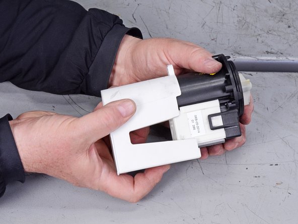
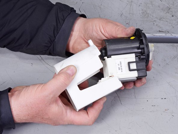
- Pull the plastic pump housing off of the motor and remove it.
- Set this housing aside, as you will need to reinstall it on the new pump motor.