HP 15-ef RAM Replacement
ID: 160478
Description: Use this guide to replace or upgrade the RAM in...
Steps:
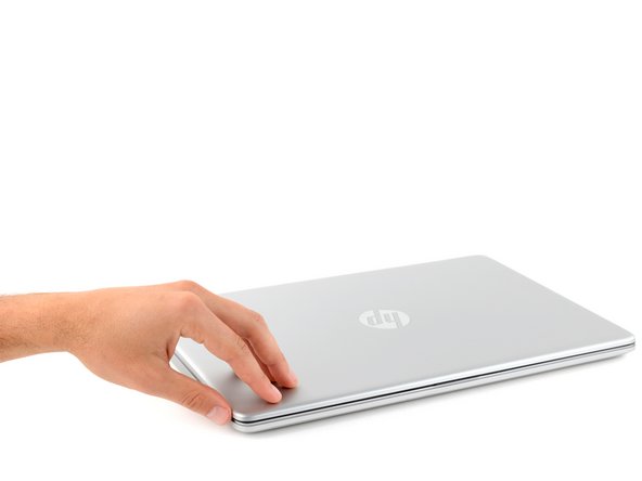
- Fully shut down your laptop and unplug all cables.
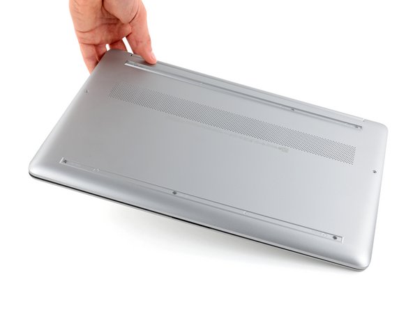
- Flip your laptop over so the rubber feet are facing up.
- The rubber feet cover a total of six back cover screws.
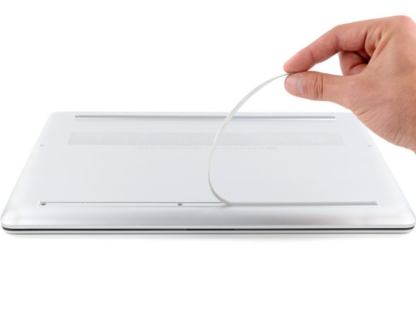
- Use an opening pick to peel up an end of the front rubber foot until you can grip it with your fingers.
- Make sure both the foot and its adhesive peel up together, as they need to be removed as one piece.
- Peel the front foot away from the back cover and remove it.
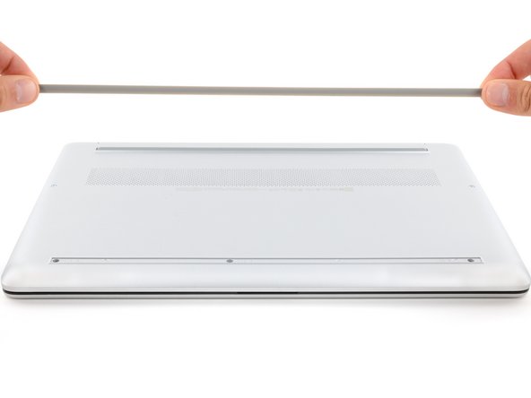
- Use an opening pick to peel up an end of the rear rubber foot until you can grip it with your fingers.
- Peel the rear foot away from the back cover and remove it.
- Note that the rubber feet are different:
- The rear foot is thicker, with a deeper recess.
- The front foot is thinner, with a shallower recess.
- During reassembly:
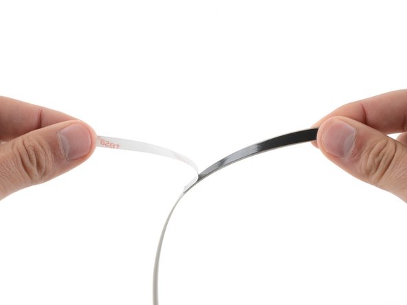
- If you're reusing the rubber feet, the leftover adhesive should be tacky enough to reuse.
- If the leftover adhesive isn't sticky enough or your replacement feet didn't come with adhesive, you can use double-sided tape such as Tesa Tape to secure the feet.
- Make sure the strips of tape aren't wider than 6 mm, otherwise they may not fit.
- To install a foot, remove its adhesive liner, lay the foot into its matching recess, and press down firmly along the entire length of the foot to secure it.
- Use a Phillips screwdriver to remove the eight screws securing the back cover:
- Six 6.5 mm-long silver screws
- Two 6.7 mm-long black screws
- Despite the standards, Phillips screwdrivers can vary in size and shape—two drivers labeled as the same size may fit differently in the same screw. Use the size that fits the most snug into the screw head to avoid stripping it.
- Flip your laptop over and open the screen.
- Plastic clips secure the back cover to the frame. You'll hear and feel the clips release as you work.
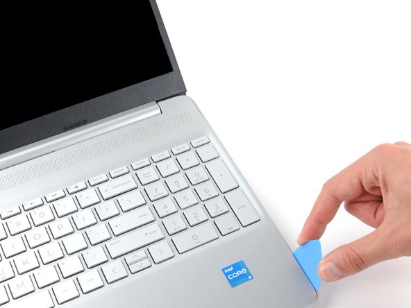
- Insert the flat side of an opening pick into the seam between the top left edge of the back cover and the frame.
- Slide the opening pick down to the bottom left corner to release the clips on the left edge.
- Avoid using excessive force when prying near the SD card slot, as it's a weak point in the case.
- Insert the flat side of an opening pick into the seam between the top right edge of the back cover and the frame.
- Slide the opening pick down to the bottom right corner to release the clips on the right edge.
- Insert the flat side of an opening pick between the bottom right corner of the back cover and frame.
- Slide the opening pick to the bottom left corner to release the remaining clips.
- Close the screen and flip your laptop back over again.
- Remove the back cover.
- To reinstall the back cover, lay it on the frame and firmly press down around the perimeter to engage all of the clips.
- Given the design of the battery connector, the only way to disconnect the battery is to physically remove it.
- Try not to bend, crease, deform, poke, or puncture the battery with your tool—a damaged battery is a potential fire hazard.
- Use a Phillips screwdriver to remove the five 3.7 mm-long screws securing the battery.
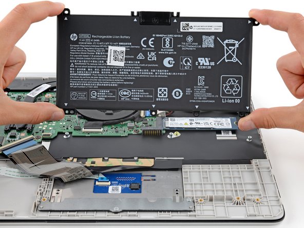
- Gently lift the upper edge of the battery to disconnect its socket from the motherboard.
- Remove the battery.
- During reassembly, use the alignment posts to position the battery and press down on the socket to secure it.
- Never reuse a deformed or damaged battery—it's a fire hazard. Replace it with a new battery.
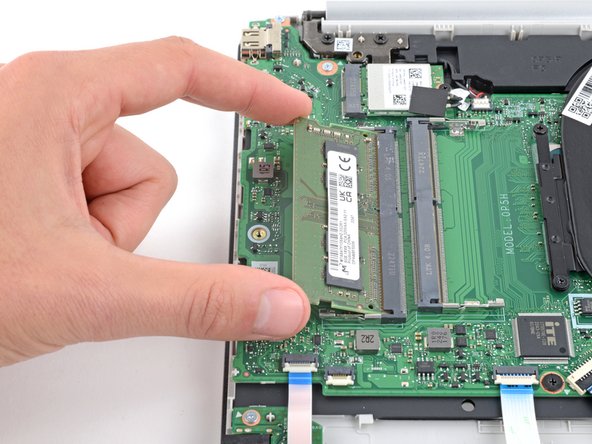
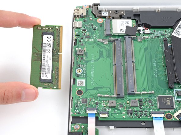
- Your laptop has two memory slots, each with a pair of metal arms that secure a stick of RAM.
- Simultaneously push out the metal arms on each side of a stick of RAM until they disengage and the stick pops up at a slight angle.
- Pull the stick of RAM out of its socket to remove it.
- Repeat for a second stick of RAM.
- To install a memory module, insert it into its socket at a slight downward angle, then push down firmly until both metal arms lock the RAM in place.