SteelSeries Arctis 7 2019 Edition Wireless Broken Micro USB to USB C upgrade Replacement
ID: 160882
Description: This Guide is on how to upgrade your...
Steps:
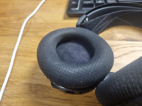
- Remove Ear Cushions
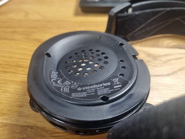
- Use the Torx T6H Bit to remove the screws
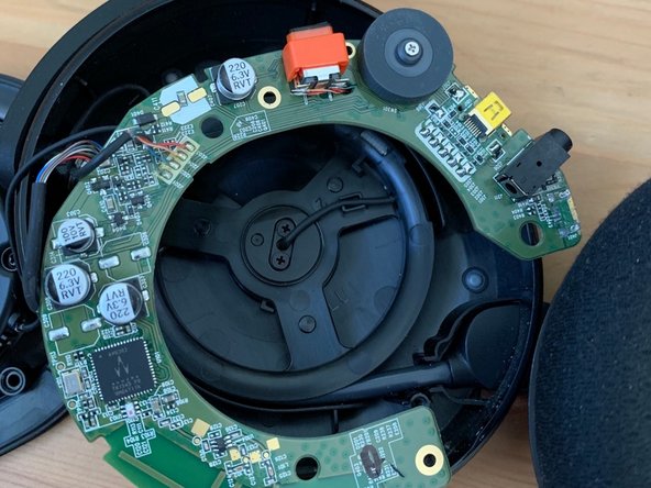
- Gently lift the speaker side. Watch out for the Cables
- Take out the Circuit Board
- Pushing on the Volume knob helps to get it out
- Source of the image: https://www.reddit.com/r/steelseries/com...
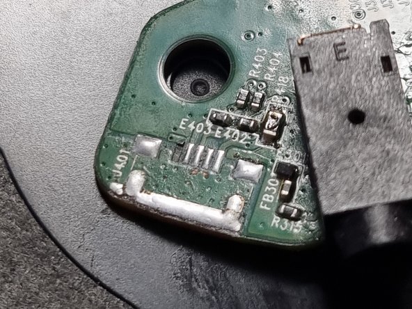
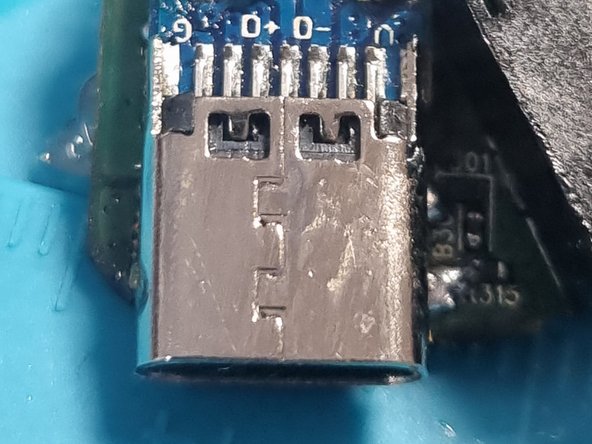
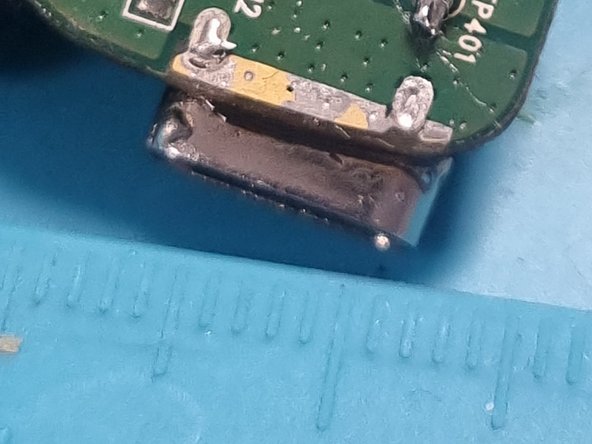
- Remove and clean the Micro USB solder spot
- My Micro USB has been ripped out. That's why I'm missing my pad
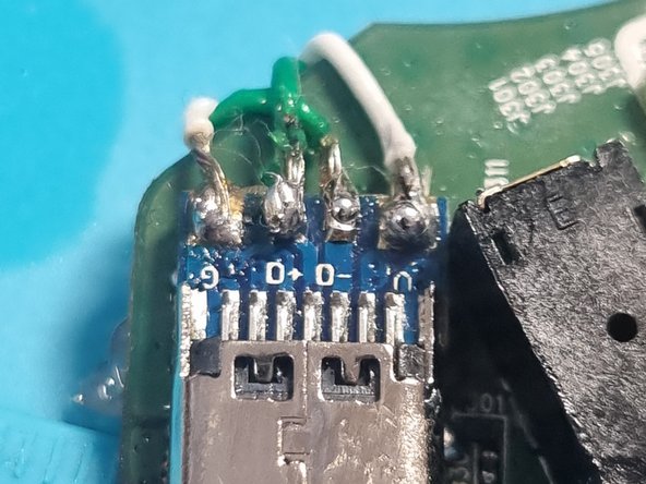
- The pins are From left to right:
- 1. VCC
- 2. D-
- 3. D+
- 4. ID
- 5. GND
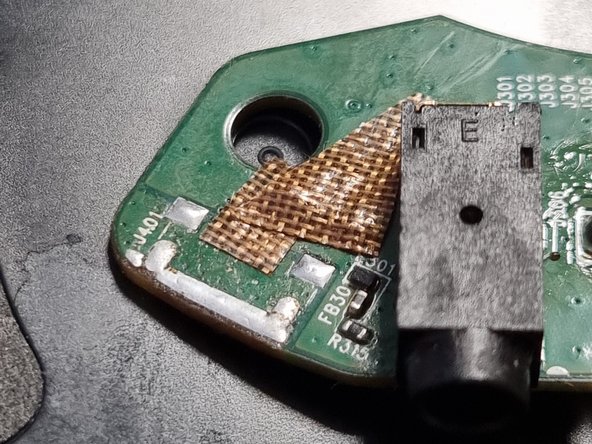
- Use Kapton Tape to cover the Electric Components
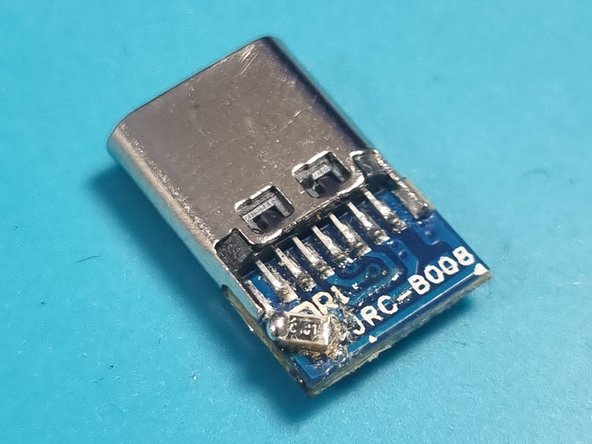
- Add a 5.1 kOhm Resistor on between R1 and GND to configure the USB-C as a slave
- Cover the open Pads with Kapton Tape
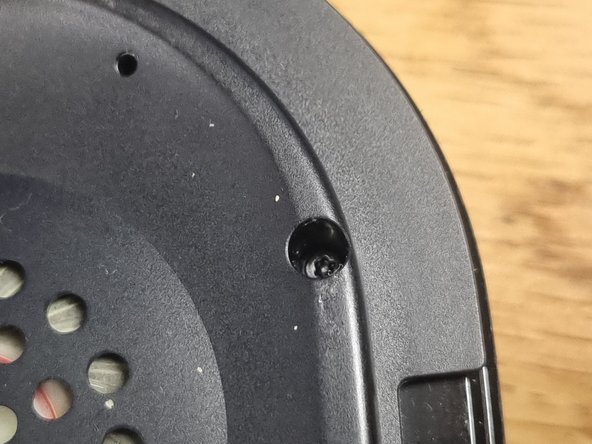
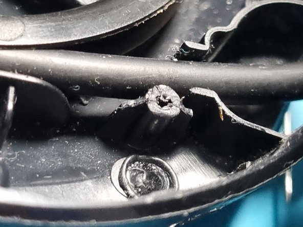
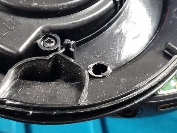
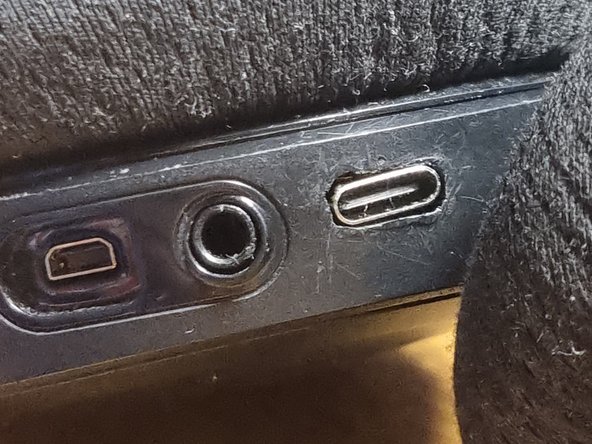
- Trim the plastic from the bottom screw hole on both the top and bottom halves of the case to make place for the port.
- Note this may impact the robustness of your device. I did not notice any drawbacks
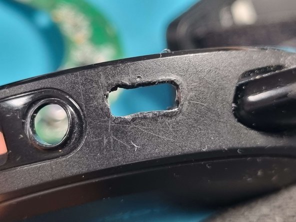
- Enlarge the micro USB cutout with a soldering iron
- Lowering the temperature of your soldering iron gives you better control when enlarging the hole
- Use isopropyl alcohol to clean the USB-C connector and PCB
- Position the USB-C board with a 2–2.5 mm overhang from the PCB
- Preheat the USB-C board using a soldering iron or a heat gun if available. It helps in soldering as it has a large thermal mass
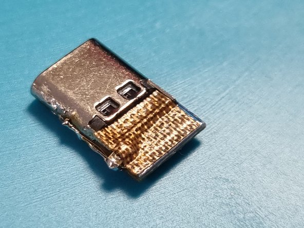
- Melt solder on the GND pads. Ensure they are fully covered and thoroughly heated
- Place the board on the GND pads. Use additional heat
- Ensure no contact between ground pads and other USB-C contacts.
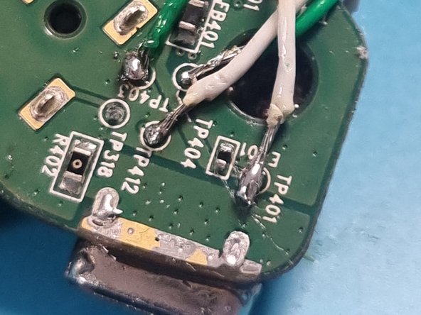
- Solder Jumper cables to the following breakout pins
- Solder Connections:
- TP401 for V
- TP403 for D+
- TP404 for D-
- TP412 for GND
- Ensure each connection is secure, has proper contact and free of shorts
- Solder the cables to the corresponding pads on the USB-C board
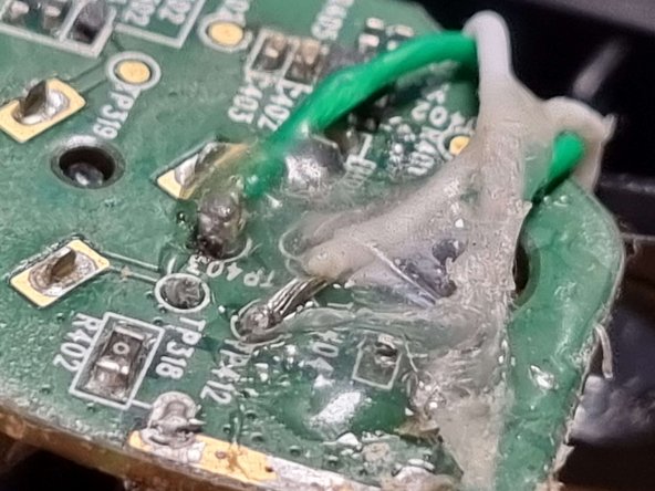
- (Optional): Add hot glue to the connections on both sides for extra stability
- Position the board in the case. Push the ports into the cutouts
- Adjust until screw holes on the case match those on the PCB
- Close the headset and fasten the srews
- CONGRATS !! You made it :D