Whirlpool WED87HED Dryer Motor Testing and Replacement
ID: 160971
Description: Use this guide to test the motor in your...
Steps:
- Before you begin your repair, unplug your dryer.
- Your power cord may have four prongs rather than three. The additional prong is a ground connection.
- Throughout this guide, keep track of each screw and reinstall it exactly where it came from.
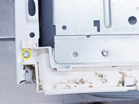
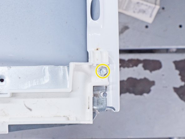
- Use a 5/16 inch nut driver to remove the two 15.7 mm-long screws securing the top panel to the rear panel bracket.
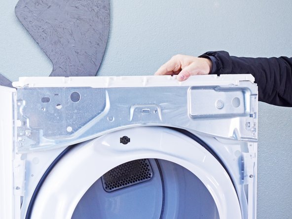
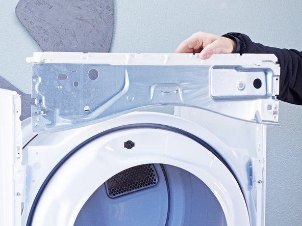
- Grasp the top and slide it 1/2 to 1 inch toward the rear of the machine.
- Lift the top panel upward to separate it from the chassis.
- Remove the top panel from the machine.
- Disconnect the control panel cable from the main board.
- Disconnect the drum light connector.
- Use a 1/4 inch nut driver to remove the two 16.3 mm‑long sheet metal screws located at each end of the control panel.
- Lift the control panel up and tilt it away from the chassis to remove it.
- Make sure to thread the cable through the hole in the chassis.
- During reassembly, thread the cable through its proper hole before reinstalling the control panel.
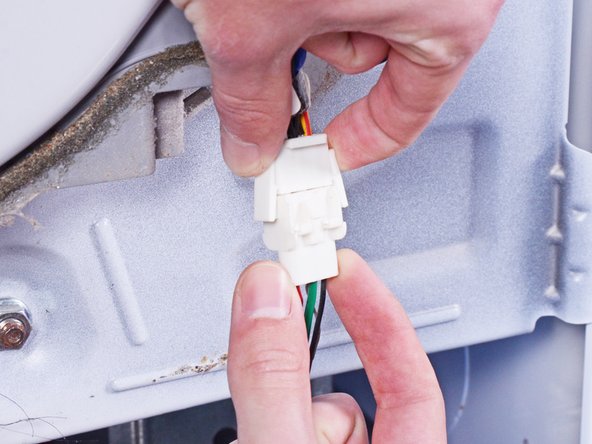
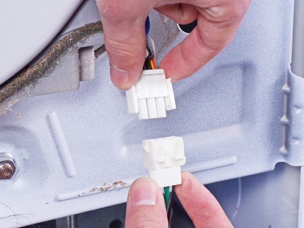
- Use a small flat blade screwdriver or a spudger to unlatch both sides of the door switch connector.
- Unplug the connector.
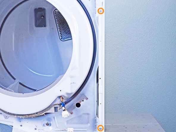
- Use a 1/4 inch nut driver to remove the three upper front panel 16.4 mm-long sheet metal screws.
- Tilt the machine backwards and prop it securely, or have a friend hold it.
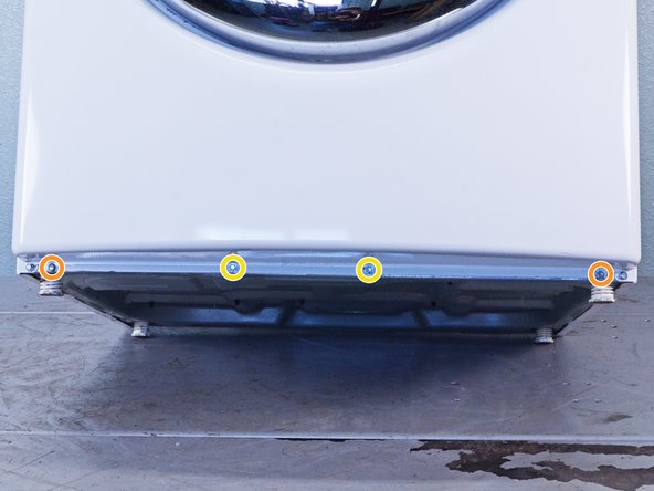
- Use a 1/4 inch nut driver to remove the four sheet metal screws on the bottom edge of the panel:
- Two 16.4 mm screws
- Two 13 mm screws
- Use a Phillips driver to remove the two 15.8 mm‑long screws inside the door area below the drum opening.
- The panel is heavy and awkward. You may want to have a friend help you with this step.
- Pull the bottom of the panel away from the chassis about two to three inches.
- Lift the front panel off the small tabs on the chassis near the top of the panel and remove it.
- Make sure you don't snag the door switch wire harness as you remove the panel.
- Use a 5/16 inch nut driver to remove the 16.2 mm-long cover plate screw.
- Remove the cover plate.
- Mark the cables with a permanent marker if needed and take a picture or draw a diagram.
- Use a Phillips driver or a 1/4 inch nut driver to remove the three 21.4 mm-long screws.
- If your plug has 4 prongs, there will be a ground connection from the cord as well. Use a 5/16 inch nut driver to remove this connection.
- Pull the cord carefully down through the round hole.
- Make sure you replace the connections correctly when you reassemble.
- Use a 5/16 inch hex driver to remove the 16.5 mm-long green ground screw.
- Use a Phillips driver to remove the two 15.3 mm‑long cord terminal block screws.
- Move the cord terminal block behind the rear panel.
- Use a 1/4 inch nut driver to remove the eleven rear panel screws.
- Ten 20 mm-long screws
- One 12.9 mm-long screw under the water inlet.
- Throughout this guide, keep track of each screw and reinstall it exactly where it came from.
- Use a 1/4 inch nut driver to remove the 16.4 mm-length screw holding the main board bracket to the chassis.
- Use a 1/4 inch nut driver to remove the two 20 mm-long screws from the top rear of the machine.
- Put on gloves before continuing, as the rear panel is sharp.
- Lift the panel about 1/2 inch and tilt it to the rear to release it from the vent pipe.
- Slide the panel off the vent pipe and remove it.
- During reassembly, perform the following:
- Make sure that the vent pipe is fitted into the collar on the panel.
- Make sure the tabs at the bottom are aligned to the bottom rim of the chassis.
- Position the panel so its screw holes match with the chassis.
- Pull the lint filter up out of the lint filter slot to remove it.
- These photos show the front panel in place, but the procedure is the same if the front panel is already removed.
- Use a 1/4 inch nut driver to remove the 16.4 mm‑long mounting screws securing the lint filter housing.
- Pull the filter housing outward from the chassis and down to remove it.
- Squeeze the locking tabs on the moisture sensor connector.
- Disconnect the connector.
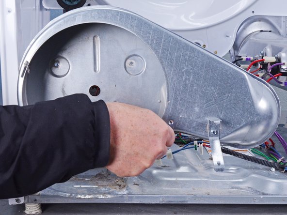
- Use a 1/4 inch nut driver to unfasten the 12.9 mm-long blower cover screw.
- Lift the blower cover slightly and slide it to free the tabs which hold it in place.
- Remove the blower cover.
- The photos show the lower front bulkhead in place. The bulkhead doesn't affect the blower cover removal and reassembly.
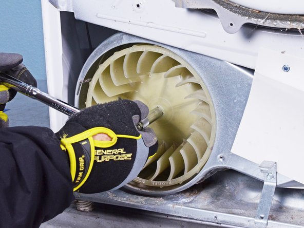
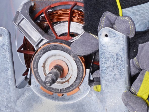
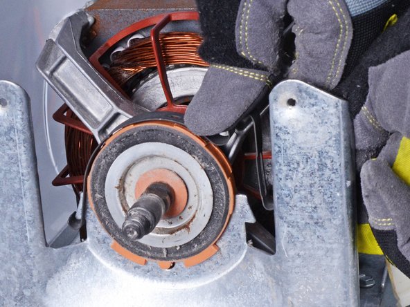
- Move to the rear of the machine to access the drive shaft.
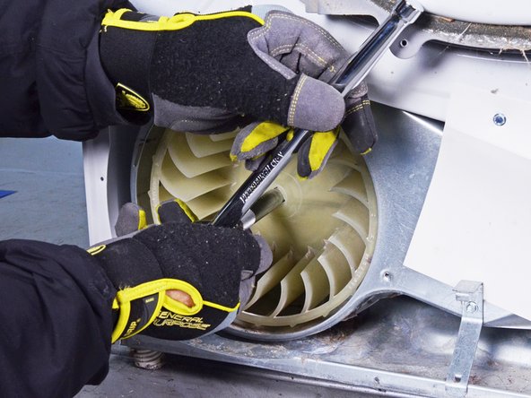
- Hold the drive shaft with an adjustable wrench, or a 1 inch wrench, on the hex portion of the drum drive pulley.
- The threads on the blower wheel are left-hand threads. The wrench must be installed to the left of the pulley to keep it from rotating counterclockwise.
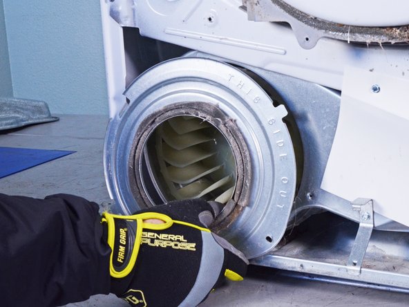
- Use a 1/2 inch drive socket wrench with a 5 or 6 inch extension bar and no socket to fit into the square hole on the blower wheel.
- Turn the wheel clockwise (to the right) to free it enough to remove it by hand.
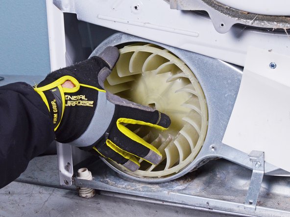
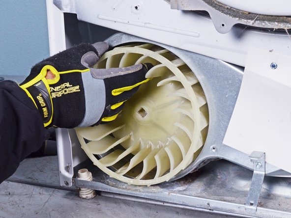
- Rotate the blower wheel clockwise by hand until it's free from the motor shaft.
- Remove the wheel from the blower housing.
- Label, photograph or make a sketch of the connector locations and of the main board bracket position on your machine.
- Disconnect all of the connectors on the main board front half.
- Label, photograph or make a sketch of the connector locations and of the main board bracket position on your machine.
- Disconnect all the connectors from the rear half of the main board.
- Use a 1/4 inch nut driver to remove the 12.8 mm‑long sheet metal screw that retains the main board to the main board bracket.
- Lift the rear corner of the main board nearest to the side walls of the chassis.
- You want to release the locking tab on the side of the main board.
- Slide the main board toward the front of the dryer to release the tabs securing it to the main board bracket.
- Remove the main board from the main board bracket.
- Use a 1/4 inch nut driver to unfasten the 16.4 mm‑long sheet metal screw holding the main board bracket.
- Lift off the main board bracket from the chassis and turn it so the bottom is exposed.
- Using long nose or slip joint pliers, pinch the locking wings of the harness retainer clamp.
- Separate the harness from the main board bracket and remove the main board bracket.
- Use a 1/4 inch nut driver to remove the two screws securing the upper front bulkhead to the front of the chassis.
- One 16.4 mm-long sheet metal screw
- One 19.8 mm-long sheet metal screw
- Use a 1/4 inch nut driver to remove the two 16.5 mm‑long sheet metal screws securing the top plastic portion to the upper front bulkhead.
- Remove the upper front bulkhead and set it aside.
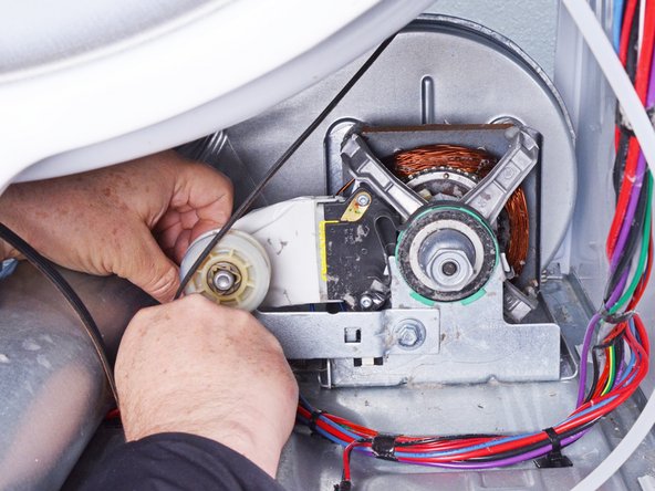
- Take careful note of the belt path before proceeding.
- Be very careful during this step! The idler arm is under spring tension and may pinch you, or it could damage the belt switch if the arm is allowed to snap down.
- Push the idler arm (the metal upside-down "L") up to relieve the tension on the drive belt.
- Remove the belt from the motor pulley.
- Gently lower the idler arm until it rests parallel to the dryer floor.
- During reassembly, refer to your notes or the belt path link to rethread the drive belt.
- Use a 1/4 inch nut driver to remove the four screws securing the lower front bulkhead.
- Two 16.1 mm-long sheet metal screws on the left side of the lower front bulkhead.
- Two 13.2 mm-long sheet metal screws on the right side of the lower front bulkhead.
- While supporting the drum, lift the lower front bulkhead off of the hooks on the chassis.
- Lower the bulkhead about 2 inches to free the drum rollers tucked under the drum.
- While supporting the drum, remove the lower front bulkhead.
- During reassembly, tilt the bulkhead to the right to get the rollers under the lip on the front of the drum. Once the drum is on the rollers, you can move the bulkhead to the upright position.
- Use the belt to lift the drum a few inches.
- Swing the drum out of the front of the dryer.
- Note which end of the drum faces the front.
- If the belt is broken, stand in front of the drum and put your arms inside it. Lift it up and pull it through the front opening of the machine. Having someone to help you with this is a good idea.
- Make sure you get your drum back on the rollers when you reinstall the lower front bulkhead. Take your time and don't force it.
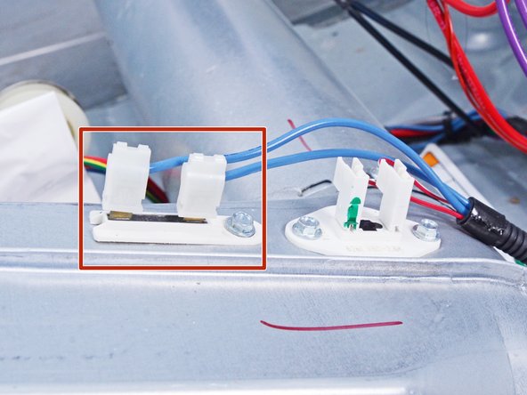
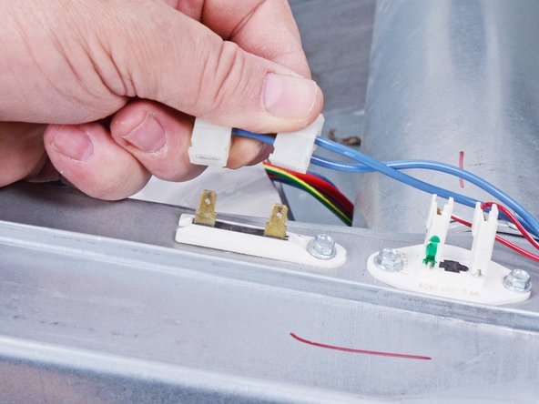
- This step shows the thermal fuse location and appearance.
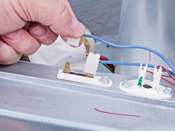
- Disconnect the two spade connectors attached to the thermal fuse.
- Always remove wires by pulling on the connector, not the wire.
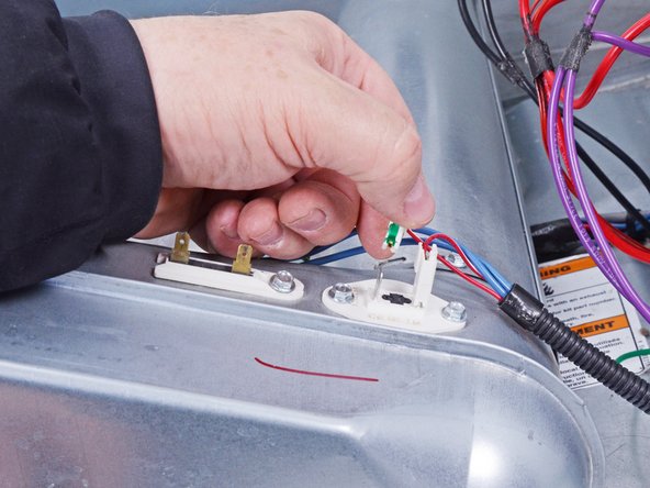
- Disconnect the two spade connectors attached to the outlet thermistor.
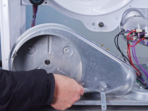
- Use a 1/4 inch nut driver to remove the 12.8 mm‑long sheet metal screw securing the vent pipe to the blower housing.
- Remove the vent pipe by sliding it toward the rear of the dryer to free it from the blower housing.
- Use a 1/4 inch nut driver to remove the three 12.7 mm‑long sheet metal screws.
- Move the blower housing toward the front of the dryer about 1–2 inches to clear the motor shaft.
- Lift the blower housing up and away to remove it.
- If you are just removing the motor without testing it, skip the next three steps.
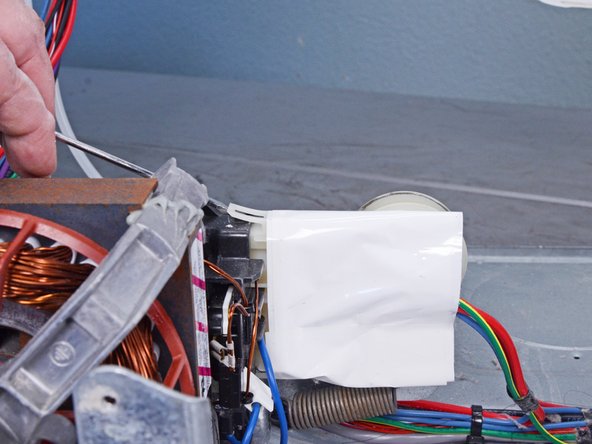
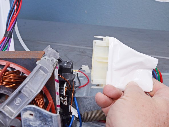
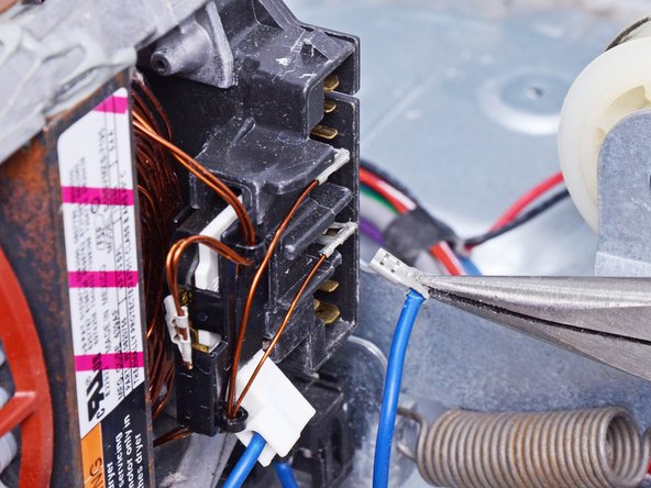
- Use a flat blade screwdriver or a spudger to lift the connector locking clips. Make sure to release both the top and bottom clips.
- Disconnect the connector by pulling it straight off.
- Be sure to grip the connectors and not the wire when disconnecting.
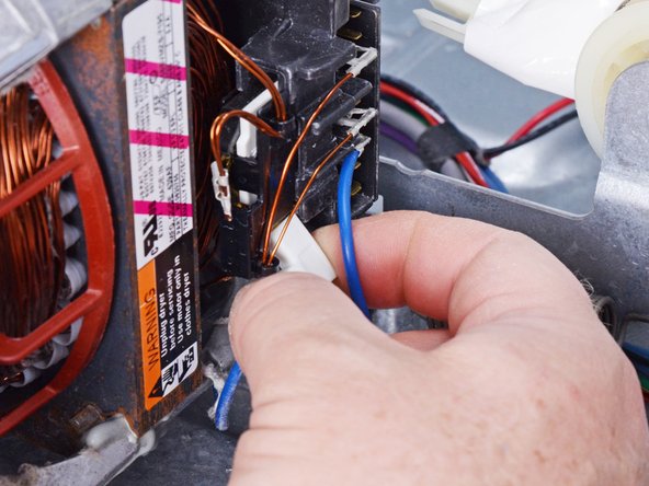
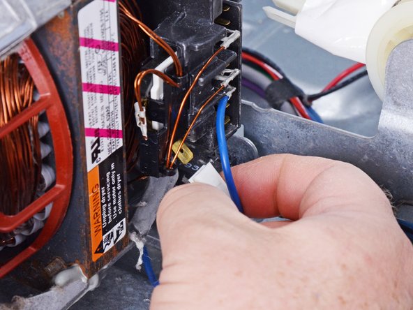
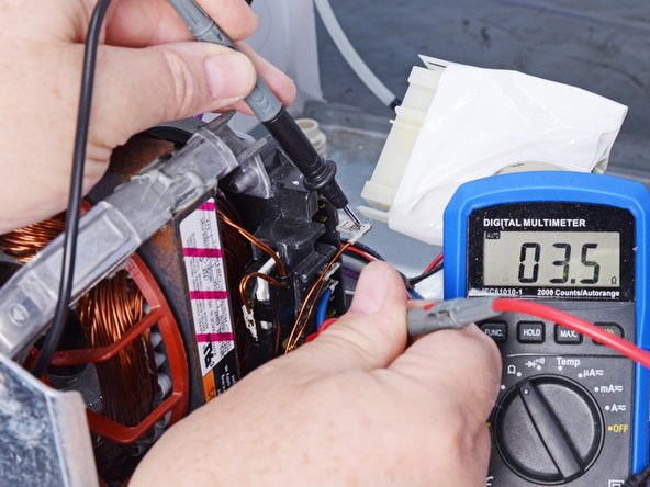
- For the next three steps refer to the first image for the terminal numbering.
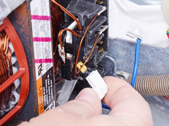
- Disconnect the blue wire with the white connector in line with terminals 4–6 that comes out at an angle.
- Be sure to grip the connector and not the wire when disconnecting.
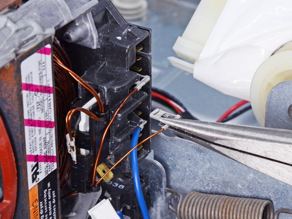
- This step will require a multimeter. If you aren't familiar with how to use one, here is a guide that will help you.
- Disconnect the lower bare copper wire aligned with terminal #3.
- Measure the resistance from the diagonal terminal (between terminals #4–#6) and the wire removed aligned with terminal #3.
- The value should be 2.7–3.0 Ω. If it's outside that range or OL, the motor is defective and needs to be replaced.
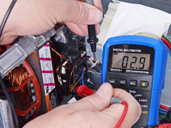
- This step will require a multimeter. If you aren't familiar with how to use one, here is a guide that will help you.
- Disconnect the top bare copper wire aligned with terminal #5.
- Be sure to grip the connector and not the wire when disconnecting.
- Measure the resistance from the diagonal terminal (between terminals #4–#6) and the top copper wire aligned with terminal #5.
- This reading should be 3.3–3.6 Ω. If it is outside this range the motor is defective and should be replaced.
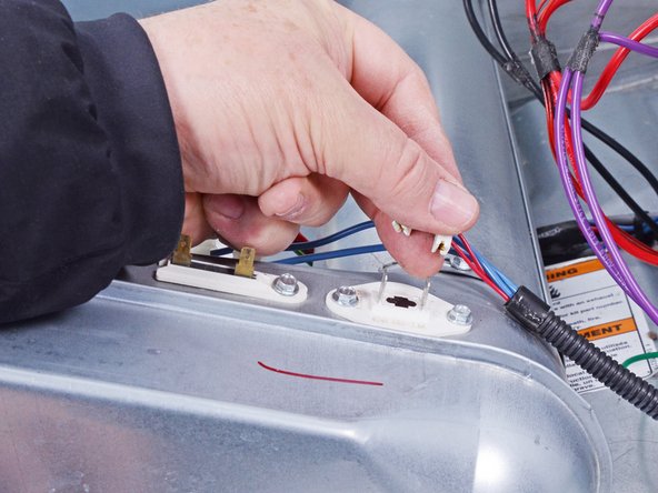
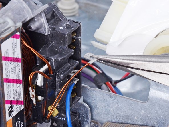
- Disconnect the blue belt switch wire with the metal connector from the motor.
- If it isn't already disconnected from checking the windings, disconnect the blue belt switch wire with the white angle connector.
- Be sure to grip the connectors and not the wire when disconnecting.
- During reassembly, refer to this photo for where to reconnect the wires.
- The next steps will show how to replace the motor.
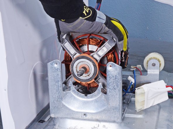
- With one hand, press down on the motor retainer clip at the bump on the clip. This should make it easy to unhook the clip from the motor cradle mount.
- While maintaining the downward pressure, use your other hand to unhook the clip from the motor cradle mount.
- Lift the motor retainer clips off the motor and remove it.
- Repeat the last two steps for the other motor clip.
- Lift the motor out of the motor mount and remove it.