Homemade Tools and Useful Spare Parts for Microwave Oven Repair.
ID: 161009
Description:
Steps:
- When repairing a microwave oven, besides the classic tools we might use (like Philips screwdrivers, Torx TT15, multimeters, etc.), there are a series of "gadgets" that can be very useful for testing, and spare parts we can salvage from other old, obsolete microwaves we've scrapped.
- You should keep in mind that the high-voltage section of a microwave oven is identical or very similar in 90% of manufactured ovens. Therefore, components we obtain from one oven will almost certainly serve us well for functional testing and component isolation in another faulty oven we might have.
- The items I'm showing you are the components I've collected in a box, along with some "useful homemade tools" that I've made myself to make checks and tests easier.
- Let's look at each tool individually to see what they are and what each one offers us.
- As well as which spare parts are worth collecting.
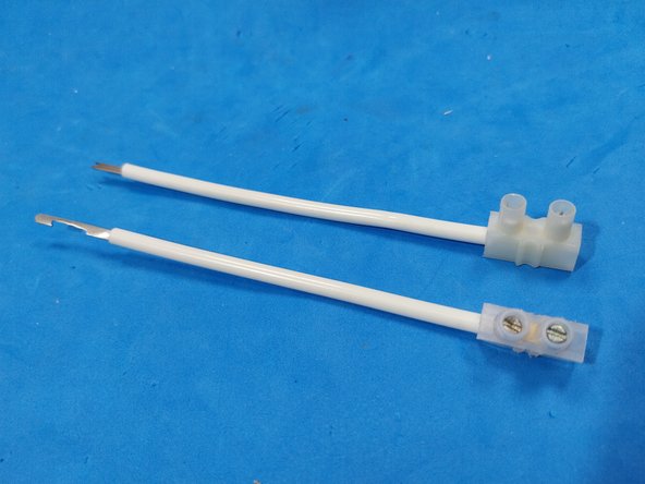
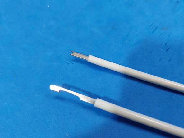
- High Voltage (HV) Fuse: The High Voltage (HV) fuse is the component that most frequently fails in microwave ovens. You'll find it installed with various types of encapsulation in most ovens. It typically connects the high-voltage output of the transformer to the high-voltage capacitor.
- The King of Microwave Failures. The high-voltage fuse is the king of microwave oven failures and can blow for two main reasons.
- Reason 1: High-Voltage Capacitor Failure. This means you actually have two problems: a blown fuse and a faulty capacitor.
- Reason 2: Internal Wire Wear. Less frequent but still possible, the fuse can blow due to simple wear of its internal wire. In this case, the solution is to replace it and test the oven again.
- Therefore, if you encounter a blown fuse, the first step is to replace it with an identical or slightly larger one. If it blows again when you test the oven, then you'll need to replace both the fuse and the high-voltage capacitor.
- Although this fuse is similar to those used in general electronics, it has LARGER physical dimensions and a working voltage of 5 KV. Its typical value is between 0.65A and 0.8A. NEVER use a fuse larger than 0.8A, and NEVER—EVER—use a piece of wire to replace the fuse. This should NEVER be done, for your safety and the safety of the oven itself.
- VIDEOS ABOUT THE FUSE: https://www.youtube.com/watch?v=Lc96Xt8w...
- HOMEMADE TOOL: That allows us to check the fuse with a multimeter in ohms scale, without removing the fuse from the microwave oven.
- EXPLANATORY VIDEO: https://www.youtube.com/watch?v=pBgEfN63...
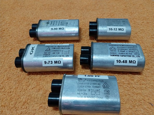
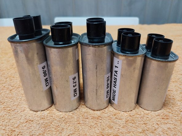
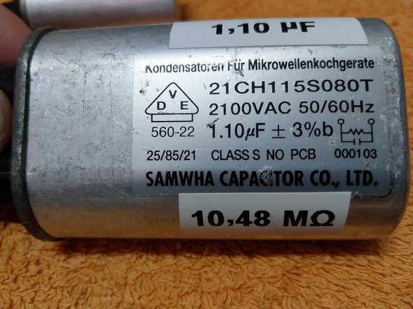
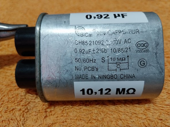
- High Voltage Capacitor (or Condenser) In Spain, it's often called "Condensador de Alta Tensión," while in many other Latin American countries, it's referred to as a "Capacitor." I'm not going to get into that debate again (I'm tired of discussing which is the correct term); everyone in their own country says it differently.
- Along with the high-voltage fuse, the high-voltage capacitor is also the king of failures in microwave ovens. Often, a damaged capacitor will blow the protective fuse, so both components would need to be replaced (two damaged items).
- The HV (High Voltage) capacitor can withstand up to 2000 or 2100 V, as you'll see indicated on its casing. It actually operates at around 1500 V. YES, YOU READ THAT RIGHT, 1500 V! This explains why it's a component that commonly fails in microwave ovens—it's a lot of voltage for an internal paper and oil dielectric.
- What kind of failures does the capacitor present?
- 1. Perforated Internal Dielectric: An "internal spark jumps" which blows the HV fuse. If you check it with a multimeter, sometimes it might show a fault, but other times it will give a false "OK" (correct) reading. This is because the spark or dielectric perforation occurs at high voltage (1500V), which the multimeter cannot measure.
- 2. Decapacitated or Low Capacity: The oven gradually stops heating. You can check this with a capacimeter.
- 3. Shorted Capacitor: The internal dielectric is completely perforated, resulting in an electrical continuity much lower than 10 MegaOhms (from the internal self-discharge resistance). It can also show a short circuit measurement between one of the poles and the metal casing, but this is less common.
- When it comes to capacitors, we need to consider three parameters, although the most important one is the MICROFARADS (uF).
- 1. Capacitor Capacity (uF - Microfarads) You can perform tests with a spare capacitor that has a slightly different uF value than the one in the oven. HOWEVER, BE CAREFUL: for a permanent replacement, you MUST use the exact same uF value that the oven originally came with.
- This is because if you vary the capacitor's value, you change the oven's operating frequency. The component that gets damaged by this change is the magnetron, which will then overheat.
- 2. Internal 10 MegaOhm Self-Discharge Resistor This is purely a safety system that discharges the capacitor within a couple of minutes when the oven is turned off. Beware: you might find older capacitors (over 15 or 20 years old) that don't have this internal resistor.
- THOSE CAPACITORS ARE DANGEROUS, AS THEY RETAIN STORED CHARGE FOR HOURS.
- 3. Capacitor Voltage This value doesn't mean the capacitor operates at 2000 V or 2100 V. Instead, it indicates that it can withstand voltages up to 2000 V or 2100 V. This makes it the least critical value, as all microwave oven capacitors can withstand at least 2000 V.
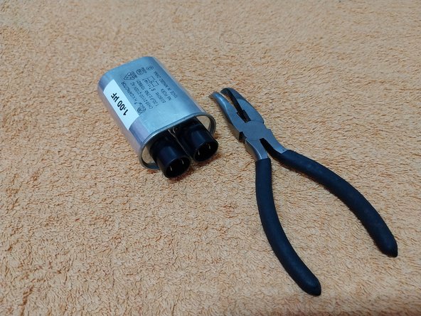
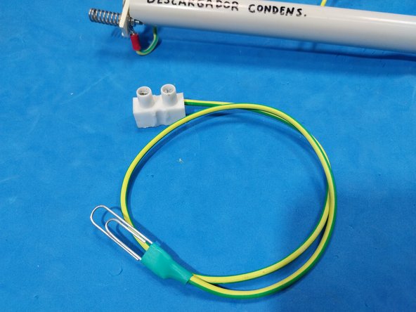
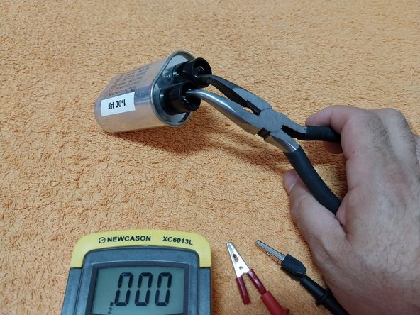
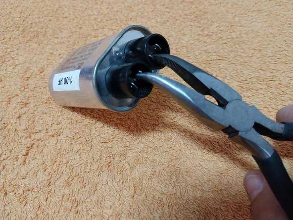
- BEFORE handling a capacitor or removing it from an oven, you MUST discharge it as a safety measure. Do this by shorting its two terminals with flat-nose pliers for 5 to 10 seconds. You can also use a wire or scissors, but flat-nose pliers are much safer and more reliable. It's also a good idea to short it twice, just to be sure.
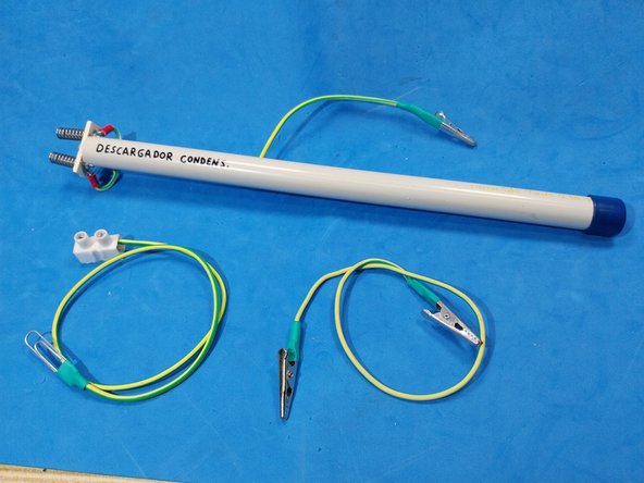
- Other examples of cables for capacitor discharge and a homemade tool I made with internal resistors.
- VARIOUS CAPACITOR DISCHARGE METHODS. VIDEOS: https://www.youtube.com/watch?v=-XVpuC-t...
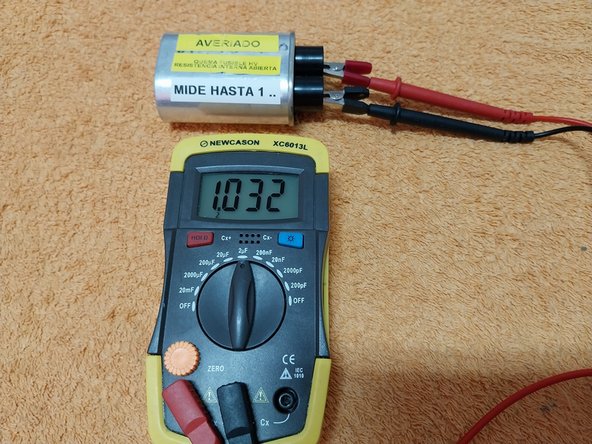
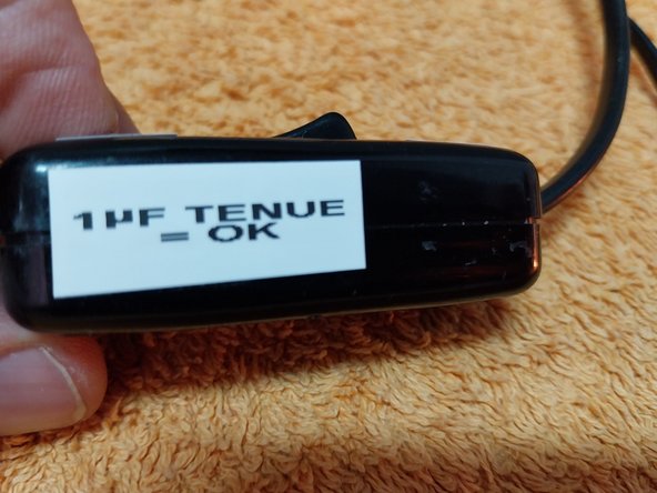
- An example of a capacitor whose microfarad measurement is correct, and it's not short-circuited (neither between terminals nor with the casing), but is still faulty.
- The only anomaly it shows is the value of its internal resistance, which reads as infinite (or 1), indicating an open circuit. This means it retains accumulated charge – DANGER!
- What's the actual fault? It has a semi-perforated dielectric. The capacitor fails when operating under high voltage, causing the voltage to arc through the dielectric and blow the high-voltage fuse.
- The fuse and capacitor have been replaced.
- The quick way to rule it out is by having a spare one for testing.
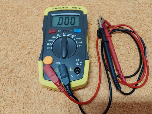
- A capacitance meter is a useful device for checking microwave oven capacitors. While it's not essential, it's definitely beneficial and adds value by allowing you to perform a real measurement of the capacitor's capacity in uF.
- There are many models and price points on the market, including multimeters that measure capacitance. This is just one example.
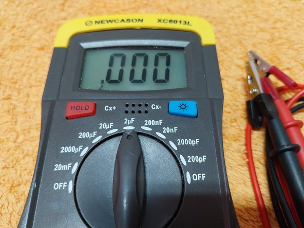
- When measuring a capacitor, even if you've discharged it before removing it from the oven, ALWAYS, ALWAYS, ALWAYS DISCHARGE IT AGAIN BY SHORTING ITS TERMINALS BEFORE MEASURING IT. This is because even a small residual voltage of just 5 or 10V accumulated in the capacitor can DAMAGE THE MEASURING DEVICE.
- All capacitance meters that end up getting damaged are because they've measured a capacitor with some accumulated voltage. Even if they haven't been used for days, DISCHARGE THEM AGAIN (SHORT THE TERMINALS WITH INSULATED PLIERS); that's the best advice I can give you.
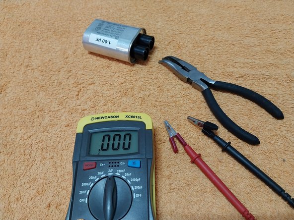
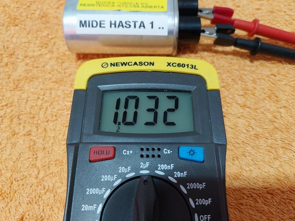
- Example of a capacitance measurement of a faulty capacitor with a semi-perforated dielectric. As you can see, the measurement is correct at 1 uF.
- That's why it's important to note that a capacitor's capacity isn't the only thing that matters. We also need to check them with a multimeter in ohms mode to test for possible shorts between a terminal and the metal casing, and to verify their internal self-discharge resistance.
- VIDEOS ON VARIOUS METHODS FOR TESTING MICROWAVE OVEN CAPACITORS: https://www.youtube.com/watch?v=LOjMQxmf...
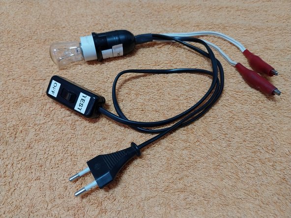
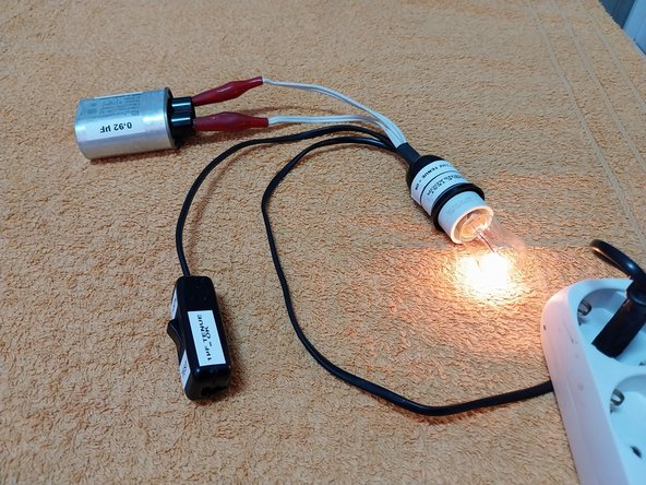
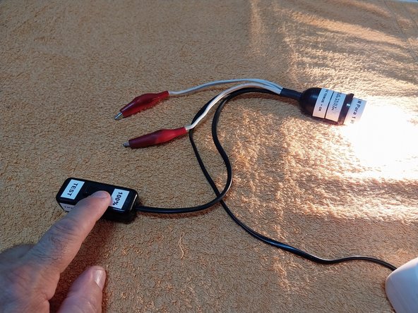
- HOMEMADE TOOL - TEST CABLE WITH LIGHT BULB This test cable, used as a series lamp, has been around for many, many years. However, NO ONE used it to test microwave oven capacitors until now.
- If anyone claims otherwise, they should show me a video dated before May 16, 2010. https://www.youtube.com/watch?v=X0kAPs0X... Since the videos weren't perfect, I did a remake, improving their quality: https://www.youtube.com/watch?v=C7QUDwV2...
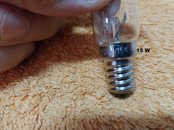
- For the microwave oven test cable, you must use a 15W FILAMENT light bulb. Pay close attention to that; ALL OTHER CFL, LED, etc., WILL NOT WORK. You can even use the light bulb from the oven itself.
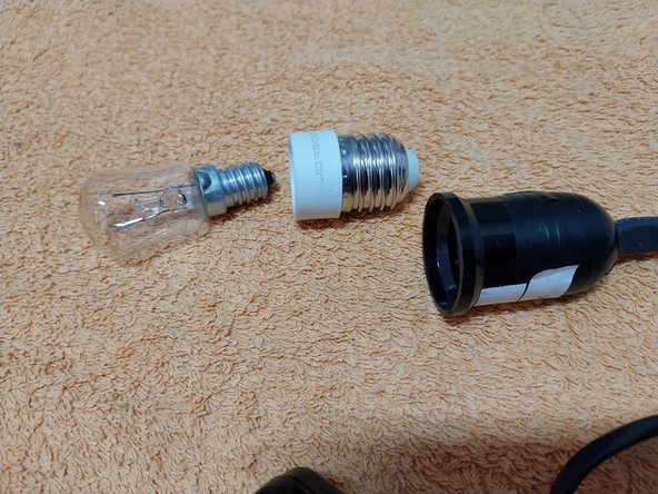
- To make the cable useful for checking other types of capacitors, I use an E27 socket with an E14 screw adapter (for a small bulb).
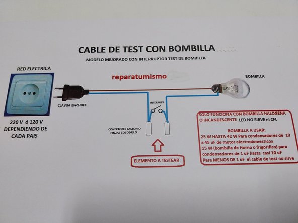
- The original basic test cable schematic, and the improved one with a switch, allow us to test the light bulb.
- The connection shown in the center of the diagram is made inside the lampholder, simply to keep it hidden and make the design more aesthetically pleasing.
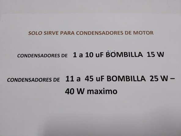
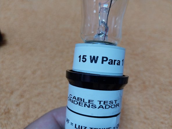
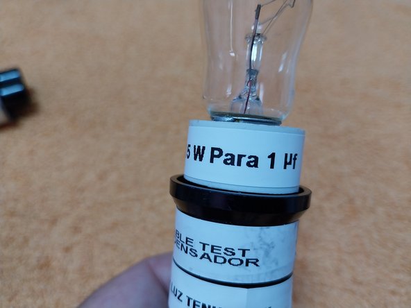
- You can use a test cable with a 15W light bulb (matching your country's mains voltage, the microwave's own bulb works fine) to rudimentarily, yet very effectively, test capacitors ranging from 0.90 uF to 1.10 uF.
- The diagram is here. https://drive.google.com/file/d/1IspqWnQ... I've updated the document about the test cable. To open the PDF, the password is: repara
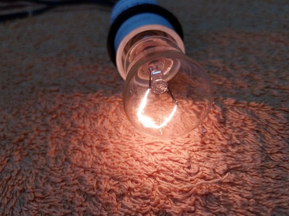
- When testing an OK capacitor, current flows through it because it's a series circuit made up of the capacitor and the light bulb. An OK capacitor will only dimly light the bulb's filament.
- With the switch open (meaning we're not bypassing the capacitor), a series circuit is formed by the capacitor and the light bulb. If the capacitor is OK, the 15W bulb will light up dimly.
- IF THE BULB DOES NOT LIGHT UP AT ALL WHEN CONNECTING THE CAPACITOR = NOK (NOT OK), CAPACITOR HAS LOW CAPACITY, DECAPACITATED = FAULTY.
- IF THE BULB LIGHTS UP 100% OR NEARLY 100% WHEN CONNECTING THE CAPACITOR = CAPACITOR WITH A PERFORATED DIELECTRIC = SHORT-CIRCUITED = FAULTY.
- VIDEOS ON CAPACITOR TESTING: https://www.youtube.com/watch?v=LOjMQxmf...
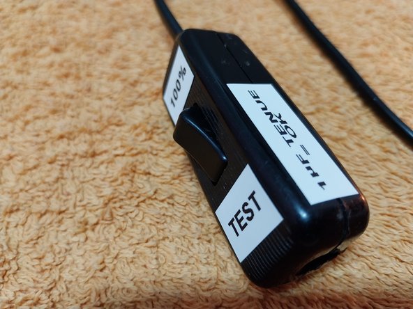
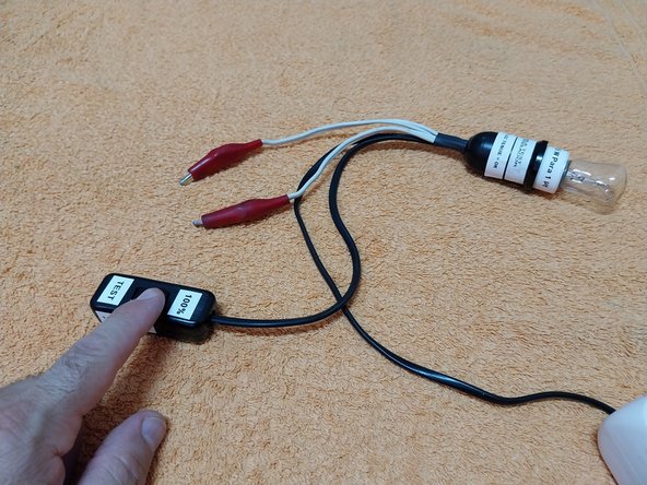
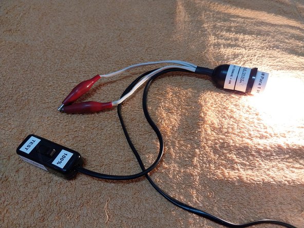
- With the knob in 100% mode (SWITCH CLOSED), all we're doing is bypassing the two alligator clips, meaning we're providing a direct power path to the bulb, so it illuminates at 100%.
- The knob allows us to check if the light bulb isn't blown. By closing the switch, it creates the exact same circuit you'd find in a bedside lamp. The switch bypasses the alligator clips; it's the same as shorting them.
- When you press the knob's switch (i.e., CLOSE THE SWITCH), you complete the circuit, and the bulb lights up at 100%.
- It's exactly the same as if we shorted the two alligator clips; we close the circuit. This is explained even better in step 17.
- For testing capacitors, you need a 15W FILAMENT light bulb. LED bulbs and low-energy CFL (compact fluorescent lamp) bulbs will NOT work. We need the bulb to have a resistive filament for a voltage drop to occur across it, which then allows the light level to vary.
- What Bulbs Are NOT Suitable for This Use:
- Oven bulbs, refrigerator bulbs, or even the microwave's own bulb are NOT suitable if they are LED or CFL type. This is because all these types of bulbs contain an electronic circuit board
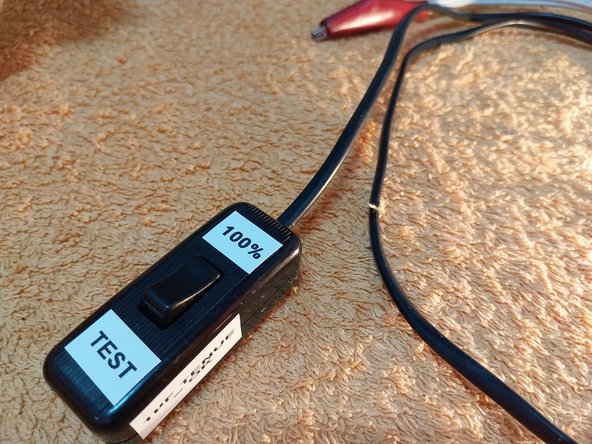
- Photo 1 Example of Use: BULB OFF if NO CAPACITOR IS CONNECTED and IF THE SWITCH IS OPEN. CAUTION: THERE IS VOLTAGE AT THE CLIPS, HANDLE WITH CARE.
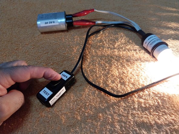
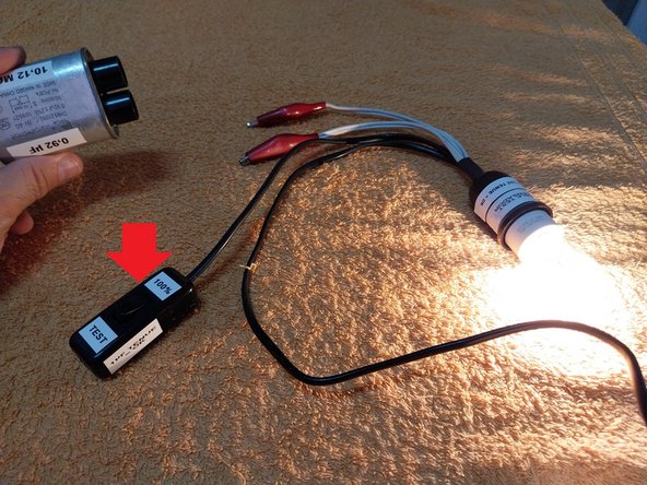
- Photo 2 Example of Use: IF WE PRESS THE SWITCH, WE SHORT THE ALLIGATOR CLIPS, WHICH MAKES THE BULB LIGHT UP AT 100%. CAUTION: THERE IS VOLTAGE AT THE CLIPS, HANDLE WITH CARE.
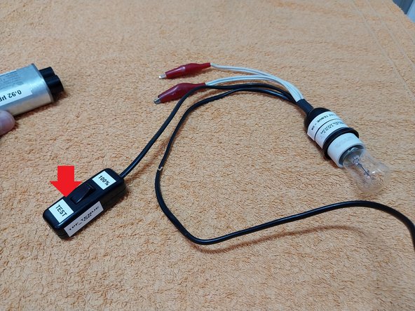
- Photo 3 Example of Use: IF THE SWITCH IS OPEN BUT WE SHORT THE ALLIGATOR CLIPS (Bulb OK Test), WE PERFORM THE SAME FUNCTION AS IN STEP 2, AND THE BULB LIGHTS UP AT 100%. CAUTION: THERE IS VOLTAGE AT THE CLIPS, HANDLE WITH CARE.
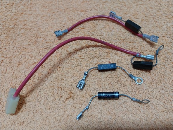
- HV diode failure isn't very common in microwave ovens, but it can happen, resulting in the appliance not heating. You can't test the HV diode directly with a multimeter. It needs to be checked with a voltage higher than 9 or 12 V DC, though there are several testing methods available.
- Various videos with different methods for testing microwave oven HV diodes: https://www.youtube.com/watch?v=UDagUJc4...
- It's very useful to save some diodes from scrapped ovens for testing purposes. SYMPTOM OF FAILURE: The oven doesn't heat up, and both the high-voltage capacitor and fuse are OK.
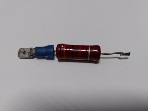
- Photo 3: 1 K ohm Resistor. This is very useful when testing the diode with voltage, preferably 48V (a printer power supply can provide this).
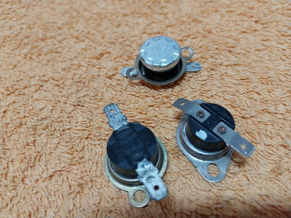
- Depending on the microwave oven model, you might find two or even three thermostats: one located on the cooking chamber, another sometimes on the underside of the chamber, and a third near the magnetron. If any of these experience an over-temperature condition, it will open, cutting off operation. Sometimes they burn out, remaining permanently open
- A thermostat is simply a temperature-sensitive switch, meaning it only has two states: CLOSED or OPEN. There are Normally Closed (NC) and Normally Open (NO) thermostats. In ovens, Normally Closed (NC) thermostats are used, which open in response to an over-temperature.
- Here are some videos on checking thermostats: https://www.youtube.com/watch?v=cRqXLI52...
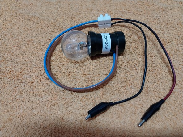
- HOMEMADE TOOL: Lamp Holder with Bulb and (2 Alligator Clips or Faston Connectors) This is an extremely useful, easy-to-build, and economical homemade tool. It allows you to visually, easily, and simply check the operation of the oven's timer (clock) and the output relay from the electronic board.
- It provides a straightforward way to confirm if power is reaching the high-voltage transformer. A faulty timer can be very easily detected visually with the bulb.
- Here's a video explaining the methodology and demonstrating the utility of this tool: https://www.youtube.com/watch?v=WrPb8-vx...
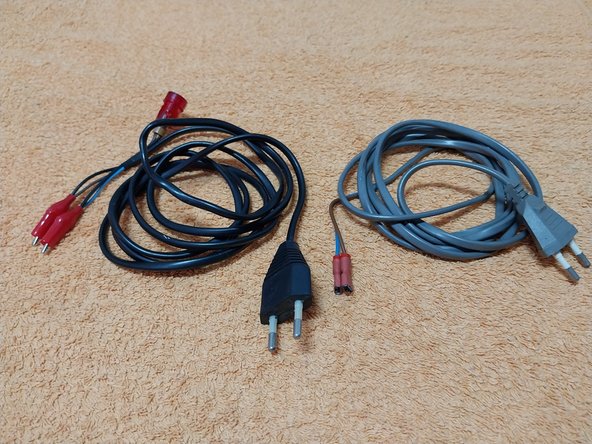
- Homemade Tool: 2 Test Cable Models I Use Here are two test cable models I use that are very useful for testing microwave oven components.
- Black Cable: This one has two alligator clips and a neon lamp at the end, which will indicate when the cable is live.
- Gray Cable: This cable has two insulated Faston terminals at the end, useful for testing components like the high-voltage transformer, for instance.
- It's also useful for testing the HV capacitor by powering it with mains voltage.
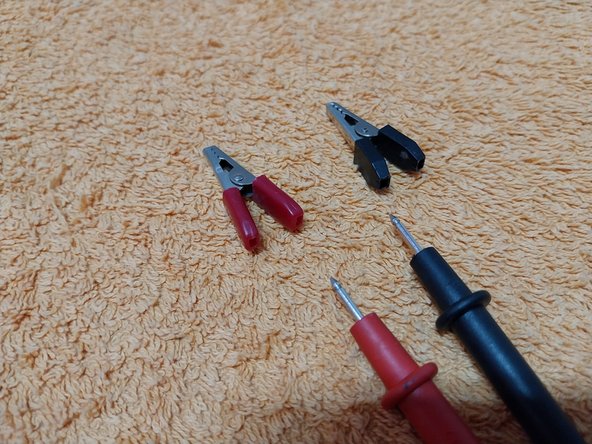
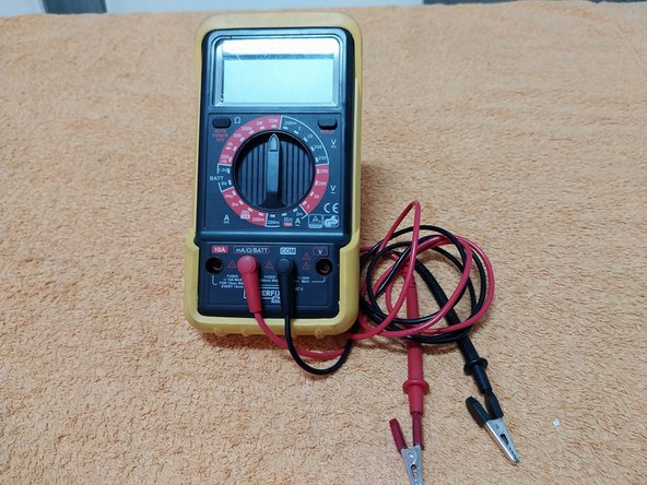
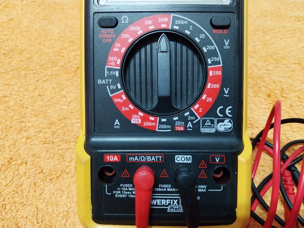
- Multimeter (or Ohmmeter, Test Meter) A multimeter goes by many names depending on the country. There's not much new to say about it, as it's a versatile tool for various measurements like resistance, AC voltage, DC voltage, and more.
- Some videos about using a multimeter: https://www.youtube.com/watch?v=l4vD14yM...
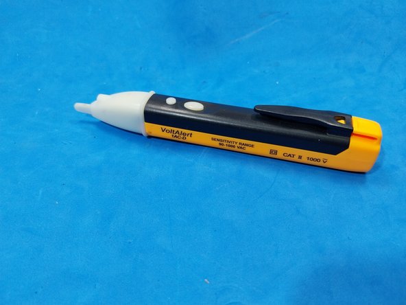
- A voltage tester pen isn't used frequently, but it can also be useful.
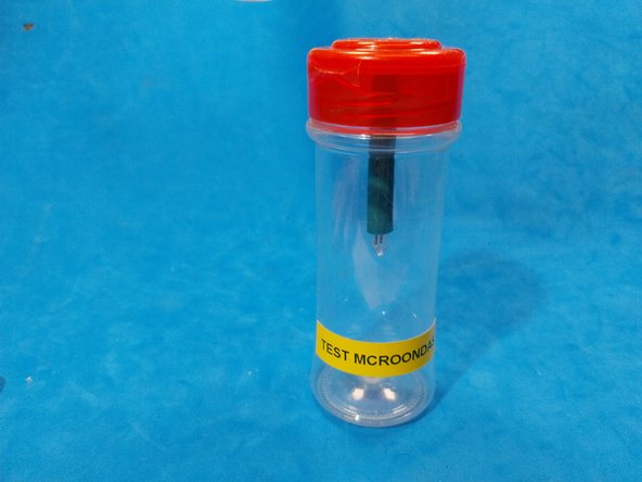
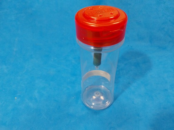
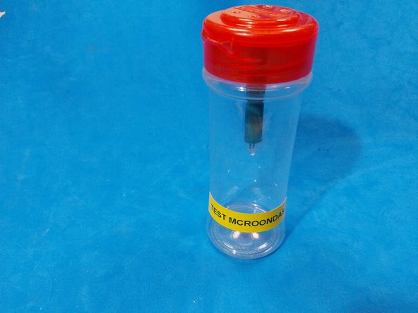
- Homemade Tools: 2 Function Testers These are two homemade testers to confirm microwave operation (specifically, if the microwave is working correctly inside the cooking chamber). One is built with a neon lamp, and the other uses a CFL tube from a light bulb. https://www.youtube.com/watch?v=gvfdlJGf...
- These two methods for checking microwave presence can only be used for an instant to avoid damaging the magnetron. They save you from having to put a glass of water in, heating it, and checking after 30 seconds if it's warmed up. With both the neon lamp and the fluorescent tube, you can see the presence of microwaves instantly.
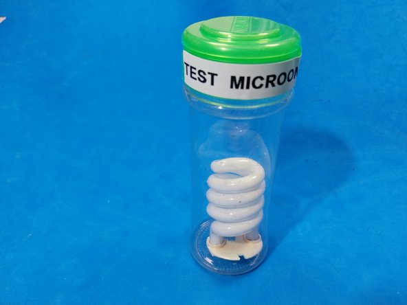
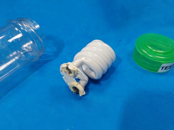
- Another Tester Using the Fluorescent Tube from a CFL Lamp: https://www.youtube.com/watch?v=v-mCNVSI...
- Both this and the previous method for checking the presence of microwaves can only be used for an instant to avoid damaging the magnetron. They save us from having to put a glass of water in, heating it, and checking 30 seconds later if it has warmed up. With both the neon and the fluorescent tube, we see the presence of microwaves instantly.
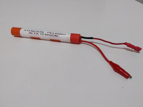
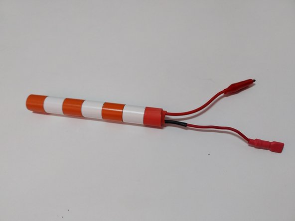
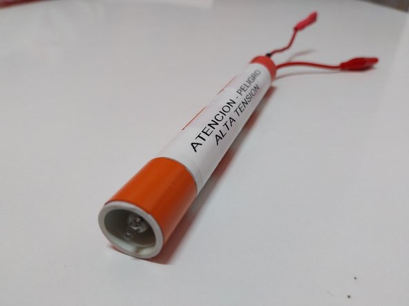
- High-Voltage Tester for Microwave Oven Transformer's High Voltage Section This tool lets you safely check if a microwave oven's high-voltage transformer has high voltage at its high-output winding.
- It's the "latest tool" I designed, as of May 9, 2023. It allows us to safely check if the microwave oven's high-voltage transformer has high voltage in its high-output winding.
- The explanatory IFIXIT document is here: https://es.ifixit.com/Gu%C3%ADa/HERRAMIE...
- Here are some videos about this tool: https://www.youtube.com/watch?v=k4HNiBZS...
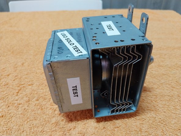
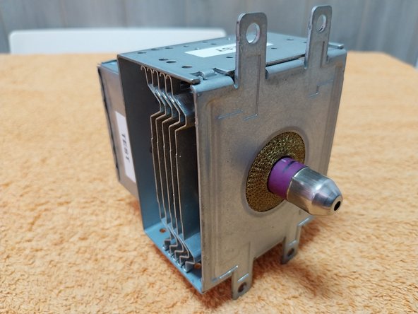
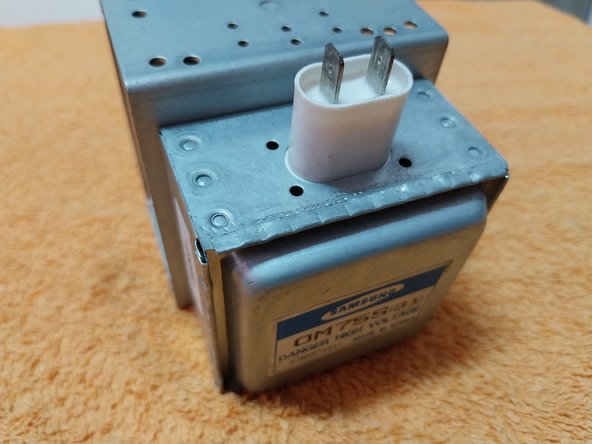
- Recycled Magnetron This magnetron was salvaged from a scrapped oven. It's very useful for testing functionality and ruling out magnetron failure.
- Although it might seem impossible, we can encounter (just like with the capacitor) a magnetron that measures OK in all respects but still doesn't work. Therefore, it's very useful to have a spare one for testing.
- Videos on the magnetron and how to test it: https://www.youtube.com/watch?v=xv9R8ilF...
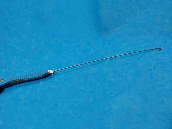
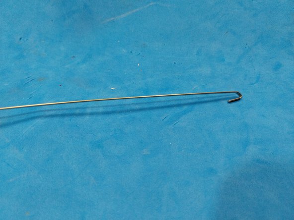
- ANOTHER HOMEMADE TOOL: This tool assists us in inserting the magnetron screws, a complicated task due to the magnetron's powerful magnet.
- Video of the tool in use: https://www.youtube.com/watch?v=JYZFqB7l...
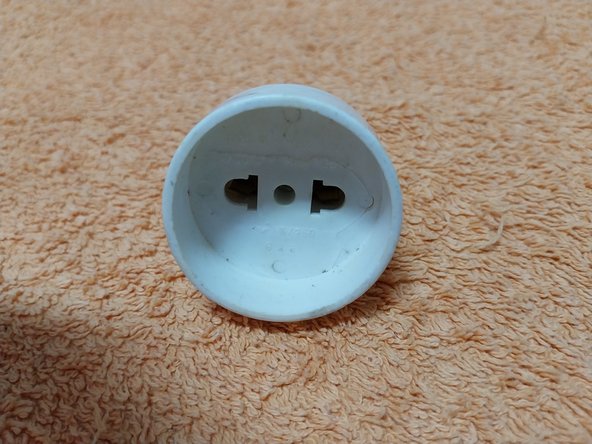
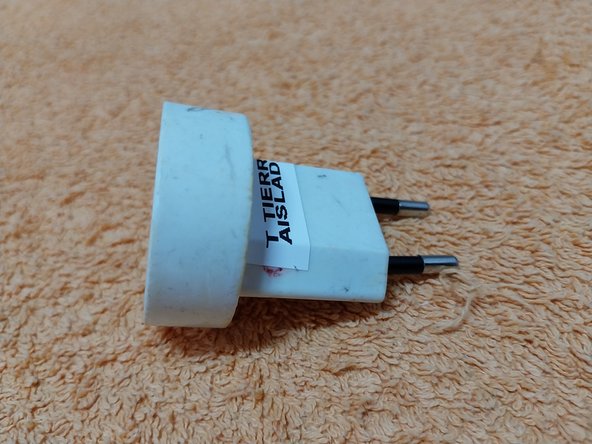
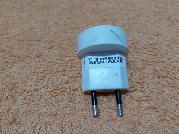
- Mains Isolator This allows us to use a Schuko plug with a ground connection without actually connecting the ground. I keep it with my tools for testing in cases of ground fault issues. Although I've hardly used it, it's sometimes useful to have it on hand.
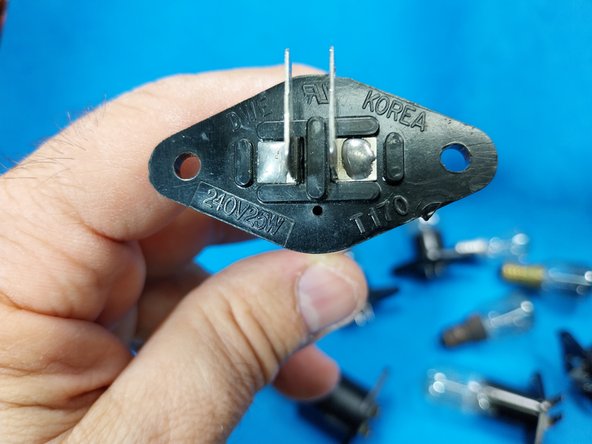
- We can also add oven light bulbs to these components, as they can help us in testing by elimination. Here are some videos: https://www.youtube.com/watch?v=TAYnLRLC...
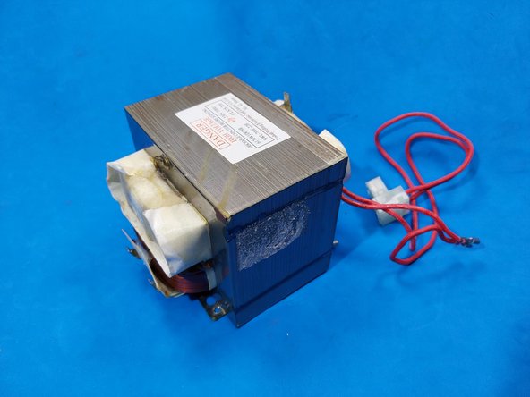
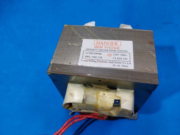
- High Voltage Transformer It's always useful to have one on hand for potential testing. Here are some videos: https://www.youtube.com/watch?v=VTrLaCVR...
- Other Recycled Elements These are additional components, salvaged from scrapped ovens, that can also assist us in testing and component diagnosis:
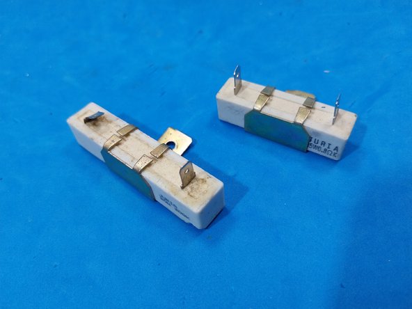
- Protection Resistors.
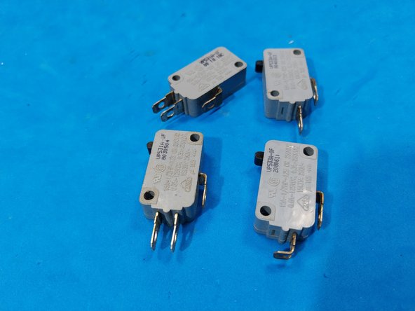
- Door Switches.
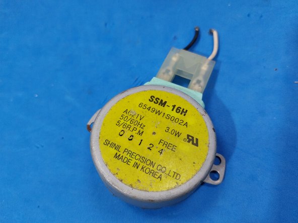
- Turntable Motor CAUTION: There are three different voltages for these motors: 230V for Europe, 21V, and 110V for countries with 110V mains.
- I don't consider this document to be finalized; it's open to improvements and the inclusion of new ideas and tools.
- I'll keep updating this information as new ideas come to me. Anyway, for those of you who want to learn more, I have a MICROWAVE OVEN REPAIR COURSE where I explain, video by video, ALL the components of a basic oven.
- VIDEOS FROM THE MICROWAVE OVEN COMPONENTS COURSE: https://www.youtube.com/watch?v=NaJqSfd5...