projectiondesign F35 scheduled maintenance
ID: 161280
Description: The GP3 series includes other projectors...
Steps:
- On the projector's right side are the two lamp doors, and the security lock hole.
- Lamps can be removed/replaced while the projector is powered on (it has 2, so the other lamp can continue projection in critical situations). But I suggest doing it with the projector off, and cooled down.
- Each lamp has a separate door. Unscrew the captive Philips screw at the top of the door and open it.
- Observe there are 3 plastic thumbscrews per lamp -- two on top and one at bottom.
- Rotate them 1/4 turn (90 degrees) counter-clockwise to unlock.
- If they are difficult to turn by hand, a large flat-head screwdriver may also be used.
- Once all 3 screws are unlocked, grasp the lamp housing from the rear protrusion, and pull. If you feel a lot of resistance, try wiggling the screws to ensure they have released.
- For the plastic thumbscrews, horizontal is locked, vertical is unlocked.
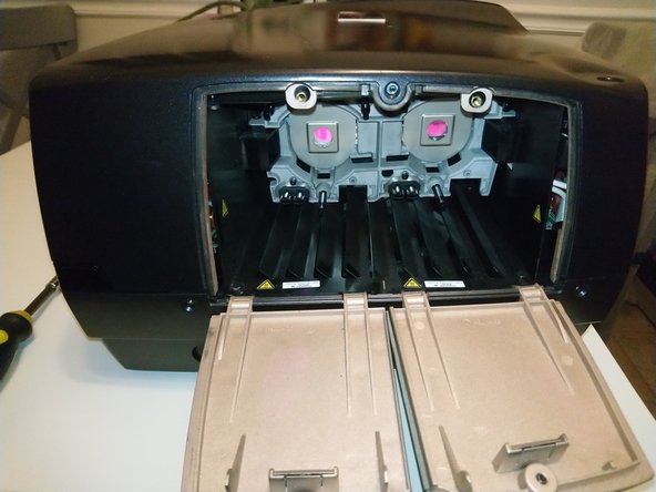
- Once the lamp is removed, you can see the three guide pins, which are held by the three thumbscrews.
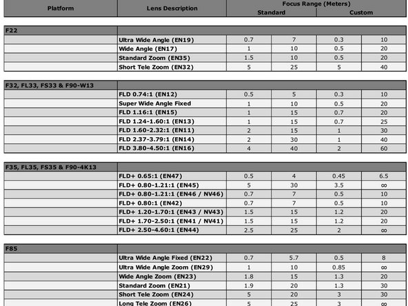
- PD manufactured many different lenses that fit these projectors. Some that zoom, others that have fixed throw ratios. There are even extra-high-quality ones for the projectors with the most pixels.
- The website projectorcentral.com lists a few ones for the F35:
- EN41 Standard Zoom Lens Throw Ratio 1.69:1-2.50:1
- EN43 Wide Zoom Lens Throw Ratio 1.20:1-1.69:1
- EN44 Short Tele Zoom Lens Throw Ratio 2.50:1-4.61:1
- EN45 Ultra Wide Zoom Lens Throw Ratio 0.80:1-1.21:1
- But these are only some of the ones available from the factory.
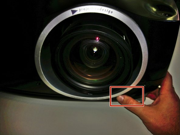
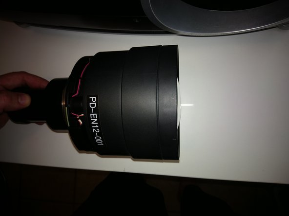
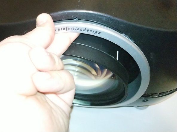
- Begin by pressing and holding the lens-release button with your right hand (or have a helper do this).
- Apologies for the very dark picture!
- Grasp the outside barrel of the lens with one or two hands, and start to rotate it counter-clockwise. Be prepared to support the weight of the lens as it is released from the locking mount.
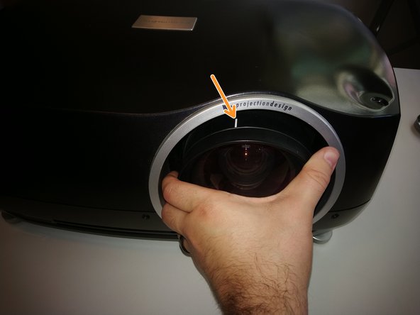
- It will rotate about 45 degrees -- watch the mark on top of the pictured lens for the start and end points.
- After rotation stops, slide the lens out of the projector.
- Be careful again that the back end doesn't drop as it slides out! The lenses are made of many heavy pieces of glass -- the weight can be surprising.
- This picture shows the view inside the lens cavity. Normally there's a shutter that closes here to protect the optical elements, but that was removed in my projector.
- You can also see the pogo pins that contact the lens ID PCB here. That will help you find the right orientation when re-installing a lens.
- Before installing a lens, make sure there are no obstructions inside the projector (like the original plastic lens mount protector), and remove any back cover or rear cap on the lens itself.
- Look at the metal mounting flange inside the projector, and at the tabs on the lens itself. There should be three tabs/slots visible.
- Two tabs/slots are about the same size -- they'll be on top when the lens slides in.
- One slot/tab will be about 2/3 the length of the others. That one goes "down" as the lens is inserted.
- Insert it such that the smallest tab of the lens mount "foot" faces down, make sure the lens is completely seated "in-plane', then gently rotate clockwise about 45 degrees -- you should hear and feel a definite tactile click when it locks into place.
- Don't force it! If it isn't rotating easily, something must be in the way.
- After removing bulbs and lens, we finally get to open up the projector.
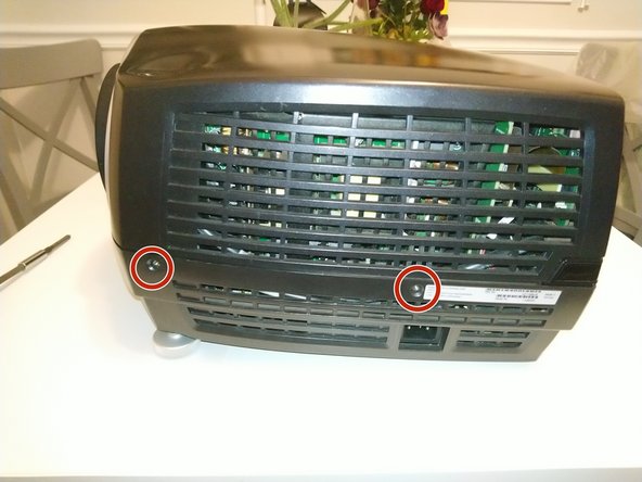
- There are 11x T10 screws holding the upper case on.
- 3 on the right (lamp) side
- 2 on the left (power) side
- 3 on the rear
- 3 on the front (see pic on next step)
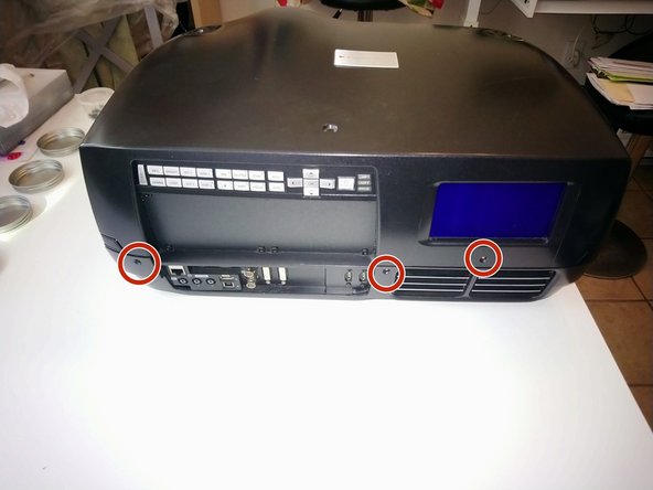
- Here are the last screws, on the front: 3x T10
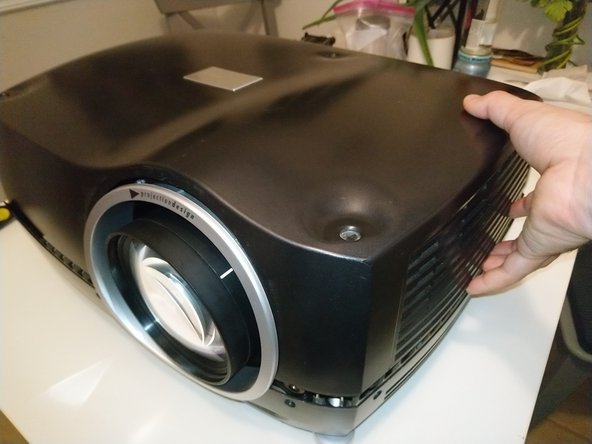
- After all the screws are removed, start lifting the case from the left and right side.
- The shell may resist being lifted off. Wiggling it gently will help, but it may also be catching around the silver lens shroud, which is a separate part.
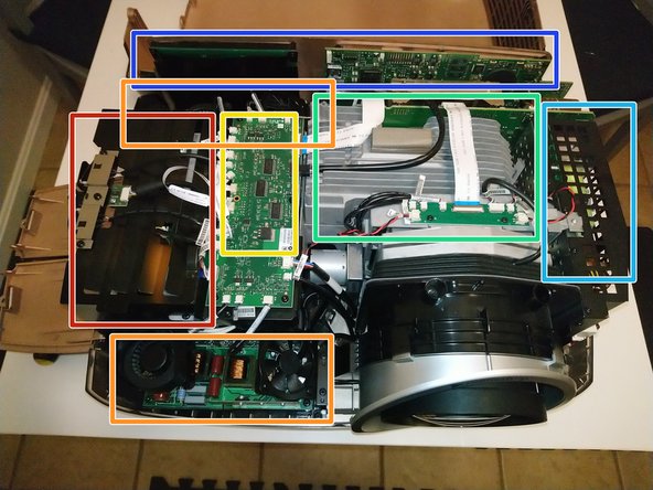
- The inside of the plastic shell has a metallic coating, which gives an attractive shiny copper sheen. Set the lid aside for later -- let's get our bearings inside!
- Lamp house (2 lamps inside)
- Lamp driver (1 for each lamp)
- Light path -- color wheels and combining prism -- under this PCB
- Image engine (including DLP device)
- Power supply
- Rear I/O panel and LCD
- Careful, though -- the coating means the inside is conductive. So, do not remove or replace the lid while the projector is connected to power!
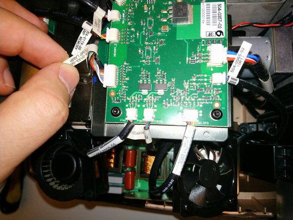
- To reach the color wheels, we must remove the lamphouse cover. This PCB doesn't actually have to be removed, but all the wires going to it must be disconnected.
- PD was very considerate in manufacturing these projectors -- there are labels on the cable and on the PCB connector.
- Starting at the large ZIF ribbon cable, and naming them clockwise, we have: IO card ribbon cable, DC POWER IO, Fan Main, IR, Fan Ctrl VDI, Fan Lamp Driver, [lamp blower fan], Temp Lamp, Lamp Memory, Lamp 2 (switch), CW2, color wheel 2 ribbon, color wheel 1 ribbon, CW1, Lamp 1, Lamp Memory, Temp Out, [lamp 1 blower fan], Fan Lamp Driver, LMP Ctrl VDI, IR2
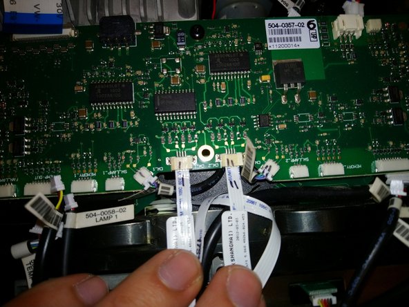
- Well, most of my cables were well-labeled. Some, though, are close together enough and similar enough to possibly be confused. So, I suggest labeling connector and cable with marker to distinguish them. See example in pic 3 -- these are ribbon cables for the color wheel motors, and the 3-wire connectors for the position sensors.
- There are 2 ventilated metal covers here, held down by 7 screws total. The IO PCB does not have to come out, but makes it a little easier to reach the screws.
- 4 screws in the color wheel /light path cover (at the top in the photo), and 3 in the lamp house cover (at bottom in photo).
- If you choose to remove the IO PCB entirely, these 5 standoffs are where the PCB screws go.
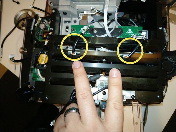
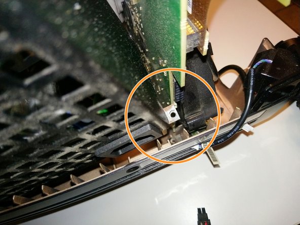
- As you lift off the lamphouse cover, carefully work around these two wires -- for the lamp hour chip readers. They connect to boards below the cover -- it's probably better to leave them connected to the IO PCB, and unplug the connectors circled here instead.
- The color wheel bracket is held down by just 3 T10 screws -- but they're about 14mm long and tricky -- especially the middle one, where you must reach through a hole in this black plastic gusset. I suggest using screwdriver with a magnetic tip here.
- Once these 3 screws are removed, the color wheel bracket will be wobbly and loose. Lift it up carefully -- the wheels are very thin optical glass.
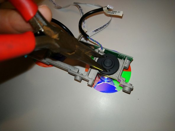
- The color wheels are mesmerizing optical glass filters. These are the "VizSim Bright" variant. They appear to reflect in a primary color (red, green, blue) but transmit light in secondary (yellow, cyan, magenta).
- Printing on the ribbon cables suggests these were made by EIS Optics, which was assimilated by Materion, who still makes color wheels and other projector components.
- The color wheels can be detached from the brackets -- the back unscrews with a pair of needle-nose pliers, or a specialized spanner -- but I did not have the tools to do that yet.
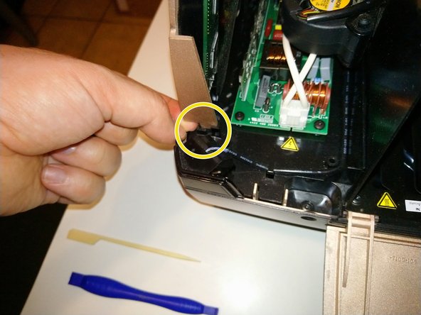
- The video and control inputs, buttons, and LCD display are all part of one assembly. To remove it:
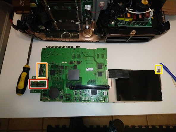
- This brown ribbon cable handles all the data going to and coming from this board. Disconnect it gently from the rear panel - a plastic spudger tool can help with this.
- There is a Molex-style power connector. Depress the lock tab, and pull it out.
- Now, lift the interface board up. It might bind on the right side where it fits into a plastic tab on the projector bottom.
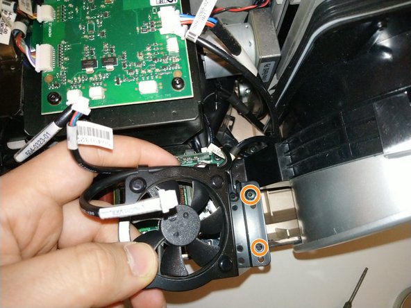
- There are two lamp driver boards, one in the front and one in the back. These provide high voltage and starting current for the lamps. Each one has a square fan mounted to a bracket.
- Remove 2x T10 screws holding each fan bracket.
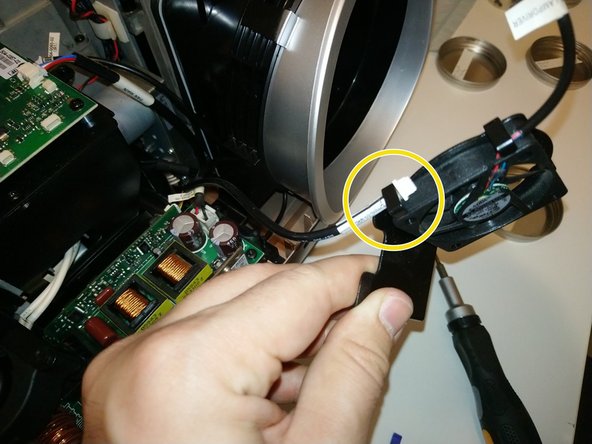
- Two cables are held in each fan bracket's cable clips. One is for the fan, but the other one needs to be disconnected and slid out from the clips.
- The fans are held in their brackets with four plastic push-rivets. These can be pushed out from the back with a screwdriver or small punch -- if you are careful, they can be reused to mount the new fans.
- The lamp driver PCBs do not have to be removed, but all wires need to be disconnected. Each board has:
- A 2-pin low voltage connector from the power supply
- A small 3-pin connector, on the vertical daughter board
- A 2-pin white connector, carrying high voltage into the lamps.
- I suggest tucking the white lamp connector back inside the lamp house to keep it out of the way.
- If removing the PCB, each one is held by 4x T10 screws.
- The front driver PCB has a plastic insulator on one of its mounting screw posts. Be careful to not lose it!
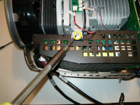
- Disconnect 2 Molex-style power cables. If it's too difficult to reach them, wait until you've got all the screws out and are starting to lift the power supply away.
- Undo 2x black T10 screws
- Undo 1x silver T9 screw, at the top
- There are a couple more notes before removing the power supply -- see next step.
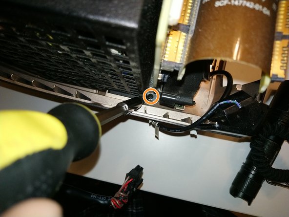
- There is a 4th screw tab on the power supply, but my unit had no screw here. Your experience may differ.
- Tilt the power supply out slightly, to clear the bracket at the top, then slowly lift up to remove.
- It may help to bend the plastic bottom shell of the projector away, gently, to help free the main AC power socket.
- When lifting the power supply out, pay attention to the rear screw tab. It's sharp metal, and is very close to the back of a large PCB. Don't scrape it (or worse, knock small components off)!
- To remove the heart of the projector, three sets of screws must be removed.