Lenovo ThinkPad X270 SSD Replacement
ID: 161319
Description: Use this guide to replace or upgrade an M.2...
Steps:
- Allow your laptop's battery to drain below 25% before starting this repair—a charged battery may catch fire if damaged.
- Unplug all cables and fully shut down your laptop.
- A SIM eject tool or bit isn't long enough to eject the tray.
- Insert a straightened paper clip into the micro SIM card tray hole on the right edge of the laptop.
- Press the paper clip firmly into the hole to eject the tray.
- Remove the tray.
- When reinserting the tray, slide the arms of the tray into the rectangular metal slot.
- Lay your laptop upside down to access the external battery.
- Two sliding tabs secure the battery.
- Slide the left tab, labeled 1, to the unlocked position—it'll click into place and release the left side of the battery.
- Hold the right tab, labeled 2, in the unlocked position and slide the battery out of its recess.
- During reassembly, slide the battery into its recess until both tabs engage.
- Never reuse a deformed or damaged battery—it's a fire hazard. Replace it with a new battery.
- Use a Phillips screwdriver to loosen the eight captive screws securing the back cover.
- Don't try to completely remove the screws—they're secured to the back cover with delicate, plastic clips.
- Plastic clips secure the back cover to the frame. You'll hear and feel the clips release.
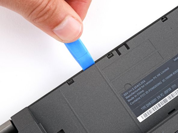
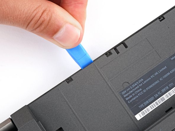
- Insert the flat side of an opening pick between the bottom right edge of the back cover and frame.
- Pry up the back cover to release the bottom right clips.
- Leave the pick inserted in the bottom right corner.
- During the next two steps, position your pick downward at a 45-degree angle to help release the clips.
- Slide the pick to the bottom left corner to release the bottom clips.
- Insert your pick in the bottom left corner and slide the pick to the first USB port to release the left clips.
- Insert an opening tool between the top left corner of the back cover and frame.
- Pry the back cover up to release the clips securing its top left corner.
- Repeat the process on the top right corner.
- Five clips secure the top edge of the back cover.
- Insert an opening tool in the gap between the back cover and frame, next to one of the clips.
- Push the opening tool into the gap until the clip releases.
- Push the opening tool between the back cover and frame at different points along the top edge to release the remaining clips.
- Remove the back cover.
- During reassembly, lay the back cover on the frame and press firmly around the perimeter to engage all the clips.
- Push on alternating sides of the internal battery connector with a spudger to "walk" it out of its socket.
- Use a Phillips screwdriver to remove the 3.7 mm‑long screw securing the SSD enclosure to the frame.
- Gently lay the SSD enclosure over the left edge of the laptop.
- Use a spudger or your fingers to reposition the black and red speaker cable so you can access the SSD cable's socket on the motherboard.
- Insert the point of a spudger under the metal locking clip that snaps around the perimeter of the SSD cable’s socket.
- Swing the clip up and over the socket.
- Gently pull the SSD cable straight out of its socket.
- Lay the SSD enclosure upside down on your work surface.
- Use a Phillips screwdriver to remove the two 3.7 mm‑long screws securing the SSD cover.
- Remove the SSD cover.
- Use a Phillips screwdriver to remove the 3.1 mm‑long screw securing the SSD to its enclosure.
- Hold the SSD enclosure down firmly against your workspace with one hand and pull the SSD straight out of its socket with your other hand.
- Don't pull up at a sharp angle, as this could damage the SSD and its socket.