Lenovo IdeaPad 310-15IKB Motherboard Replacement
ID: 161433
Description: Use this guide to replace the motherboard in a...
Steps:
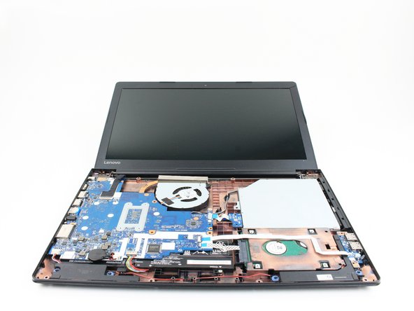
- Flip the laptop over with the hinge facing away from you.
- Use a Phillips screwdriver to remove the twelve 6.5 mm screws that secure the lower case and the right panel.
- It's not necessary to remove the lower left panel unless you intend to replace the HDD.
- Insert the flat end of a spudger into the notch on the upper left corner of the right panel.
- Pry the panel up to release the retaining clips that secure the panel.
- Remove the panel.
- Use a Phillips screwdriver to remove the three 6.6 mm screws that secure the motherboard to the lower case.
- Use tweezers or your fingernails to lift the fan cable connector directly up and out of its motherboard socket.
- Use the flat end of a spudger or a fingernail to flip up the ZIF locking flaps on the keyboard and trackpad connectors.
- Use blunt tweezers to pull the keyboard ribbon cable directly out of its socket.
- Use blunt tweezers to pull the trackpad ribbon cable directly out of its port.
- Grip and pull the blue pull tab, not the entire ribbon cable.
- Use the pointed tip of a spudger to gently pry up and disconnect the two antenna cables from the wireless card.
- Flip the laptop over and open the lid.
- The keyboard assembly is secured to the lower case by plastic retaining clips. You'll hear and feel them release as you work.
- Insert the tip of an opening pick into the seam between the top left corner of the lower case and keyboard assembly.
- Slide the opening pick down to the bottom left corner to release the clips.
- Insert the tip of an opening pick into the seam between the lower left side of the palm rest and the lower case.
- Slide the opening pick to the right to release the clips that secure the front edge.
- Insert the tip of an opening pick into the bottom right seam between the chassis and keyboard assembly.
- Slide the pick toward the top right corner to release the remaining retaining clips.
- Lift the keyboard assembly off of the chassis.
- Use two opening tools or your fingernails to gently "walk" the battery connector directly out of its motherboard socket.
- Use a Phillips screwdriver to remove the four 3.3 mm screws that secure the motherboard to the lower case.
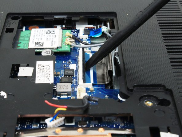
- Use the flat end of a spudger to flip up the ZIF locking flap that secures the display cable.
- Use blunt tweezers to pull the display cable directly out of its motherboard socket.
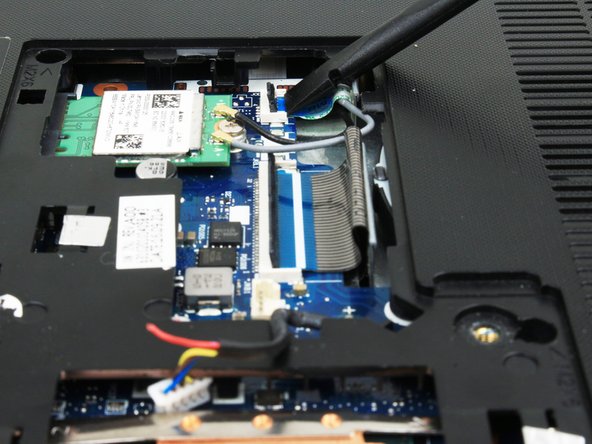
- Use blunt tweezers to lift the display cable vertically to unseat it from the motherboard.
- The display cable is attached to the motherboard with a mild adhesive. Lift gently to avoid damaging the cable.
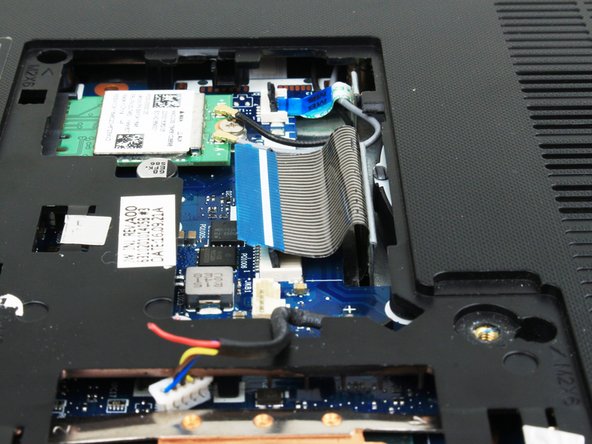
- Use the pointed end of a spudger or your fingernails to gently "walk" the speaker cable directly out of its motherboard socket.
- Use the flat end of a spudger to flip up each of the two ZIF locking flaps that secure the HDD and I/O board ribbon cables to the motherboard.
- Use blunt tweezers to disconnect the the HDD and I/O board ribbon cables from their motherboard ports.
- Grip and pull the blue pull tabs, not the entire ribbon cable.
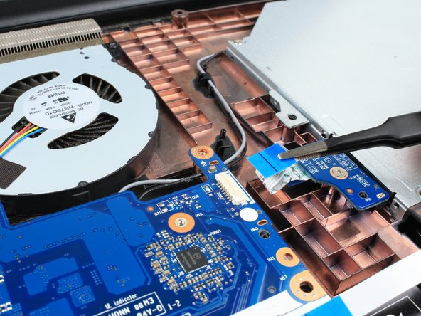
- Use the flat end of a spudger to flip up the ZIF locking flap that secures the optical drive ribbon cable.
- Use blunt tweezers to gently pull the optical drive ribbon cable directly out of its motherboard port.
- Grip and pull the blue pull tab, not the entire ribbon cable.
- Slightly lift the right side of the motherboard.
- Slide the motherboard a few millimeters to the right to unseat the ports from the lower case.
- Grasp both sides of the motherboard and lift it up and out.