Google Pixel Fold Base Vibrator Replacement
ID: 162759
Description: This repair guide was authored by the iFixit...
Steps:
- Allow your battery to drain below 25% before starting this repair. A charged battery may catch fire if damaged.
- Fully power off your phone and unplug any cables.
- Lay the phone down on a clean, smooth surface so the back glass is facing up.
- Heat an iOpener and apply it to the bottom edge of the back glass for two minutes.
- You can also use a hair dryer, heat gun, or hot plate—but extreme heat can damage the displays and/or internal batteries, so proceed with care.
- The next three steps demonstrate the Anti-Clamp, a tool we designed to make the opening procedure easier. If you aren't using the Anti-Clamp, skip down three steps for an alternate method.
- For complete instructions on how to use the Anti-Clamp, check out this guide.
- Pull the blue handle backwards to unlock the Anti-Clamp's arms.
- Unfold your phone completely and slide the Anti-Clamp arms over the left edge of the back glass, below the Google "G" logo.
- Position the suction cups near the bottom edge of the phone—one on the front, and one on the back.
- Make sure the suction cup on the inner screen isn't touching the bezel, as it won't stick properly.
- Squeeze the cups together to apply suction to the desired area.
- If you find that the surface of your phone is too slippery for the Anti-Clamp to hold onto, you can use tape to create a grippier surface. If the glass if cracked, use packing tape to help the suction cups adhere.
- Place an object under your phone, like a box or a stack of books, so it rests level while between the Anti-Clamp's arms.
- Pull the blue handle forward to lock the arms.
- Turn the handle clockwise 360 degrees or until the cups start to stretch.
- Make sure the suction cups remain aligned with each other. If they begin to slip out of alignment, detach the suction cups and realign the arms.
- Insert an opening pick into the gap under the back glass.
- If the Anti-Clamp doesn't create a sufficient gap, apply more heat to the area and rotate the handle a quarter turn.
- Don't crank more than a quarter turn at a time, and wait one minute between turns. Let the Anti-Clamp and time do the work for you.
- Skip the next step.
- Apply a suction cup to the back glass, as close to the center of the bottom edge as possible.
- Pull up on the suction cup with strong, steady force to create a gap between the back glass and the frame.
- Insert an opening pick into the gap.
- Depending on the age of your phone, this may be difficult. If you're having trouble, apply more heat to the edge and try again.
- If your back glass is badly cracked, covering it with a layer of clear packing tape may allow the suction cup to adhere. Alternatively, very strong tape may be used instead of the suction cup. If all else fails, you can superglue the suction cup to the broken back glass.
- Don’t insert the opening pick deeper than 3.5 mm when separating the back glass adhesive, as you risk damaging internal components.
- Slide the opening pick back and forth along the bottom edge to separate the adhesive.
- Leave the opening pick in the bottom left corner before continuing.
- Apply a heated iOpener to the left edge of the back glass for two minutes.
- Rotate the opening pick around the bottom left corner to separate the adhesive.
- Insert a second opening pick at the bottom left corner.
- Slide the opening pick toward the top left corner to separate the adhesive.
- Leave the opening pick in the top left corner before continuing.
- Apply a heated iOpener to the top edge of the back glass for two minutes.
- Rotate the opening pick around the top left corner to separate the adhesive.
- Insert a third opening pick in the top left corner.
- Slide the opening pick toward the top right corner to separate the adhesive.
- Apply a heated iOpener to the right edge of the back glass for two minutes.
- This sharp corner is very fragile. Use plenty of heat and be very gentle around the corner during this step.
- Angle your pick so it's as flat as possible to the back glass.
- Rotate the opening pick around the top right corner to separate the adhesive.
- Insert a fourth opening pick in the top right corner.
- Slide the opening pick toward the bottom right corner to separate the adhesive.
- This sharp corner is very fragile. Use plenty of heat and be very gentle around the corner during this step.
- Angle your pick so it's as flat as possible to the back glass.
- Rotate the opening pick around the bottom right corner to separate the adhesive.
- Don't fully remove the back glass yet, as it's still connected to the phone by a cable.
- At this point, the back glass should be separated from the frame. If there's still resistance around the edges, use an opening pick to separate any remaining adhesive.
- Swing the left edge of the back glass up and over the right edge of the phone.
- Lay the back glass to the right side of the phone before continuing.
- Throughout this repair, keep track of each screw and make sure it goes back exactly where it came from.
- While the Pixel Fold uses Torx Plus screws, standard Torx bits also work. Use the same size or one size larger (T3 or T4 Torx bits with 3IP Torx Plus screws) and apply constant, downward force to prevent stripping.
- Use a Torx Plus 3IP driver to remove the two 2.8 mm‑long screws securing the middle bracket.
- Use tweezers, or your fingers, to pull the middle bracket toward the left edge of the phone and release its clip.
- Remove the middle bracket.
- During reassembly, reinsert the middle bracket clip under its slot in the frame before aligning the screw holes.
- Use the point of a spudger to pry up and disconnect the back glass cable from the motherboard.
- To re-attach press connectors like this one, carefully align and press down on one side until it clicks into place, then repeat on the other side. Don't press down in the middle. If the connector is misaligned, the pins can bend and cause permanent damage.
- Remove the back glass.
- During reassembly:
- If you're reusing your back glass, use tweezers to remove big chunks of adhesive from the perimeter of the back glass.
- Repeat for any adhesive on the frame.
- Use isopropyl alcohol (>90%) and a lint-free cloth to remove any remaining adhesive residue.
- Follow this guide to replace the back glass adhesive with custom cut strips.
- If you don't have custom cut adhesive strips, use double-sided tape, like Tesa Tape, to secure the back glass to the frame.
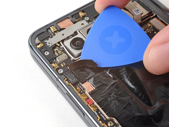
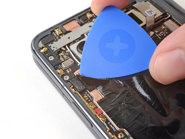
- The graphite sheet is very fragile. Be gentle peeling the graphite sheet in this step, especially if you're reusing it.
- The graphite sheet is lightly adhered to the logic board.
- Peel the bottom of the graphite sheet toward the top of the phone until you can access the bottom bracket.
- Use your hands, or tape with light adhesive, to keep the graphite sheet out of the way.
- During reassembly:
- If you completely removed your graphite sheet, follow this guide to replace it.
- If you don't have custom cut adhesive strips for the antenna, use double-sided tape, like Tesa Tape, to secure the graphite sheet to the logic board.
- Use tweezers, or a clean fingernail, to pull the black screw cover off the top screw on the bottom bracket.
- Use a Torx Plus 3IP driver to remove the five 3.1 mm‑long screws securing the bottom bracket.
- Use tweezers, or your fingers, to pull the bottom bracket toward the bottom edge of the phone and release its clip.
- Remove the bottom bracket.
- During reassembly, reinsert the bottom bracket clip under its slot in the logic board before aligning its screw holes.
- There are two batteries you need to disconnect, one for each half of the phone.
- Use the point of a spudger to pry up and disconnect the base battery cable press connector.
- Peel the grey conductive tape off the bottom interconnect cable.
- Use a point of a spudger to pry up and disconnect the flip battery and bottom interconnect press connectors.
- You have to disconnect both cables to keep the battery connector from accidentally touching the logic board.
- During reassembly, the next two steps demonstrate how to replace the flip battery and bottom interconnect cable conductive tape.
- Peel off the new conductive tape from its liner and apply the sticky side to the bottom interconnect connector, making sure to bridge the logic board.
- Use a spudger, or your fingers, to press down the conductive tape and adhere it.
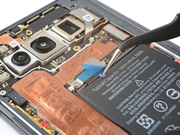
- Use tweezers, or your fingers, to pull on the tab and expose the tape.
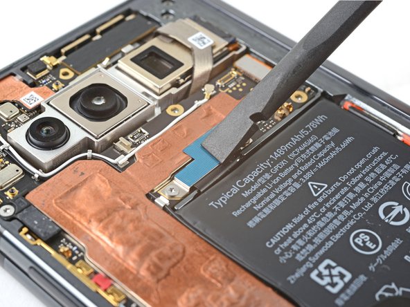
- Slide an opening pick under the top of the graphite sheet to separate the thermal insulator adhesive.
- Peel the graphite sheet off the logic board to separate the remaining adhesive.
- Remove the graphite sheet.
- If there's any remaining adhesive, use tweezers to peel it off the logic board.
- Don't pry against the battery with the spudger, as you risk damaging it.
- Insert the flat end of a spudger between the battery and the bottom speaker.
- Twist the spudger to separate the adhesive securing the bottom speaker.
- Remove the bottom speaker.
- During reassembly, if your adhesive is still intact and sticky, you can reuse it. Otherwise, follow this guide to replace the adhesive.
- If you don't have custom cut adhesive strips, use double-sided tape, like Tesa Tape, to secure the speaker to the frame.
- Be careful during this step, as you risk breaking the small surface-mounted components on the logic board. Avoid prying against the logic board.
- Use the point of a spudger to lift up and disconnect the fingerprint sensor press connector.
- Peel off the tape covering the top interconnect cable.
- During reassembly, perform the following to replace the conductive tape:
- Peel off the new conductive tape from its liner and apply the sticky side to the press connector, making sure to bridge the logic board.
- Use a spudger, or your fingers, to press down the conductive tape and adhere it.
- Use tweezers, or your fingers, to pull on the tab and expose the tape.
- Use a Torx Plus 3IP driver to remove the two screws securing the top interconnect cable:
- One 2.8 mm‑long screw
- One 2.5 mm‑long screw
- The metal bracket securing the connector is part of the press connector itself. Don’t try to remove the bracket from the connector.
- Use the point of a spudger to pry up and disconnect the top interconnect cable press connector.
- Be careful during this step, as you risk breaking the small surface-mounted components on the logic board. Avoid prying against the logic board.
- Use the flat end of a spudger to lift up and disconnect the inner screen press connector.
- Move the inner screen cable up 90° over the right edge of the phone before continuing.
- Use a Torx Plus 3IP driver to remove the two 2.8 mm‑long screws securing the middle bracket.
- Pull the top bracket toward the left edge of the phone to release its clips.
- Remove the top bracket.
- During reassembly, insert the top bracket clips under their slots in the frame before aligning the screw holes.
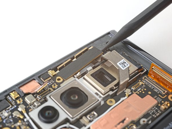
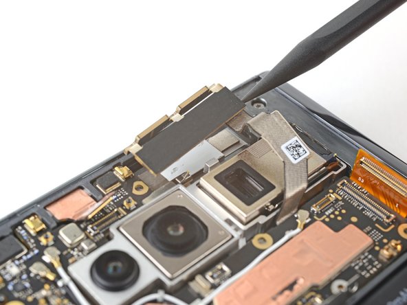
- The 5G mmWave antenna is lightly adhered to the frame.
- Insert the point of a spudger between the frame and the right edge of the 5G mmWave antenna.
- Pry up to separate the adhesive.
- During reassembly, if your adhesive is still intact and sticky, you can reuse it. Otherwise, follow this guide to replace the adhesive.
- If you don't have custom cut adhesive strips, use double-sided tape, like Tesa Tape, to secure the antenna to the frame.
- Insert the point of a spudger under the bottom right corner of the front camera press connector.
- Don't insert the spudger anywhere else, as you risk breaking surface-mounted components on the logic board.
- Pry up and disconnect the front camera press connector.
- The front camera is adhered to the frame.
- Heat an iOpener and apply it to the front camera for two minutes.
- You can also use a hair dryer or heat gun, but be careful not to overheat the phone. Don't concentrate the heat on a single spot.
- Use tweezers to grab the front camera by its connector, as close to the camera body as possible.
- Don't pinch the press connector's pins, as you may bend them.
- Pull straight up to separate the adhesive and remove the front camera.
- During reassembly, if your adhesive is still intact and sticky, you can reuse it. Otherwise, follow this guide to replace the adhesive.
- If you don't have custom cut adhesive strips, use double-sided tape, like Tesa Tape, to secure the front camera to the frame.
- Use a Torx Plus 3IP driver to remove the two screws securing the logic board:
- One 2.8 mm‑long screw near the top left corner
- One 2.5 mm‑long screw near bottom right corner
- Use tape with light adhesive, such as painter's tape, to keep the three cables out of the way before continuing:
- Fingerprint sensor cable
- Top interconnect cable
- Inner screen cable
- Don't fold the cables at a sharp angle, as you can crease the cable.
- Insert the flat end of a spudger under the top of the logic board, near the front camera recess.
- Pry up to release the logic board from its upper alignment peg.
- Be very careful during this step, as the logic board is fragile and has many cutouts in the frame. Go slowly, and don’t yank the logic board if it feels stuck.
- Grip the top of the logic board with your fingers.
- Lift the logic board upward while pulling it gently toward the right edge of the phone to release the bottom clip.
- You'll feel some resistance from the white logic board bracket. Lift slowly until it clears its slot in the frame.
- You'll also feel some resistance from the thermal paste bonding the logic board to the frame.
- Once the clip is released, lift straight up to remove the logic board from its lower alignment peg.
- Remove the logic board.
- During reassembly, perform the following to clean the thermal paste:
- Use the flat end of a spudger to scrape off the thermal paste on the bottom of the logic board.
- Clean any remaining thermal paste residue with isopropyl alcohol (>90%) and either a coffee filter or a lint-free cloth.
- Repeat the cleaning process for the thermal paste on the frame.
- During reassembly, follow this guide to reapply thermal paste to your device.
- When applying new thermal paste, use the flat end of a spudger to spread it evenly across the logic board. Try to match the original spread.
- The next four steps will demonstrate how to reinstall the logic board.
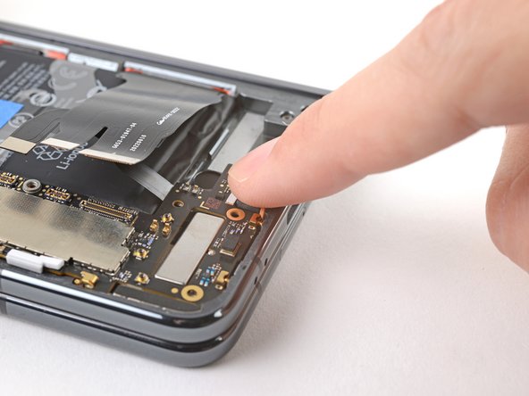
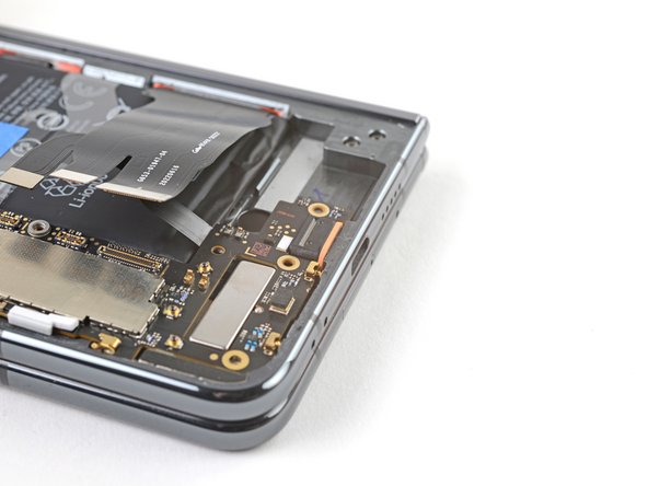
- Insert the USB-C port into its cutout in the frame at a shallow angle.
- Use your finger to press the USB-C port down until the orange rubber gasket is level with its cutout—not twisted or pinched.
- Press the bottom of the logic board over its lower alignment peg and engage its spring connectors.
- While pushing the logic board toward the bottom edge of the phone, press the logic board into its lower metal clip.
- Press down on the white logic board bracket so it rests under the lip in the frame's edge.
- Make sure all of the cables are above the logic board before securing it back into the frame. If you haven't taped them, do so now to avoid trapping them as you work.
- While pressing down on the white logic board bracket, push the logic board against the left edge of the phone.
- Position the logic board over the upper alignment peg.
- Press down to secure the logic board.
- If your graphite sheet is taped out of the way, remove the tape now.
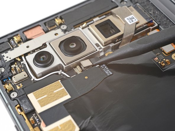
- Use the point of a spudger to pry up and disconnect the ultra wideband antenna press connector.
- The ultra wideband antenna is lightly adhered to the graphite sheet.
- Slide an opening pick under the antenna to separate its adhesive.
- Peel up the ultra wideband antenna and remove it.
- During reassembly, if your adhesive is still sticky and intact, you can reuse it. Otherwise, follow this guide to replace it.
- If you don't have custom cut adhesive strips, use double-sided tape, like Tesa Tape, to secure the antenna to the logic board.
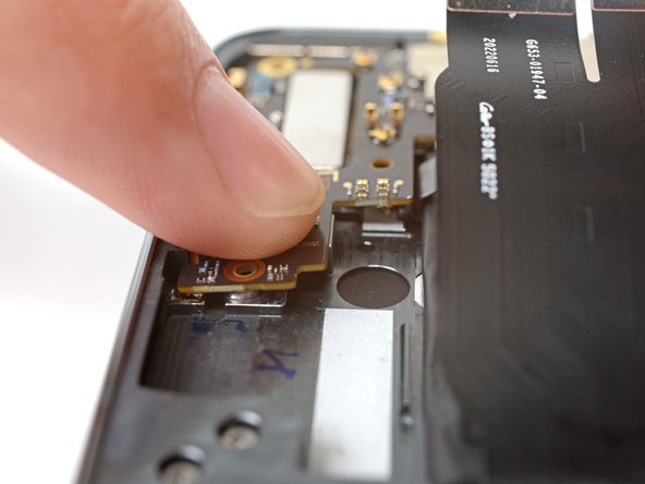
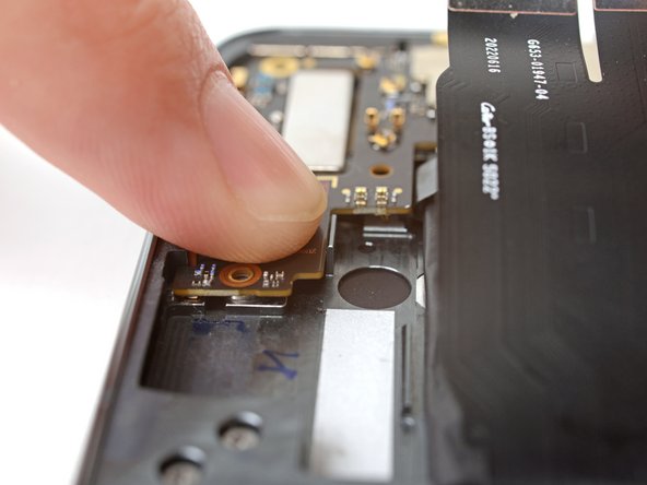
- Heat an iOpener and apply it to the base vibrator for two minutes.
- You can also use a hair dryer, heat gun, or hot plate—but extreme heat can damage the displays and/or internal batteries, so proceed with care.
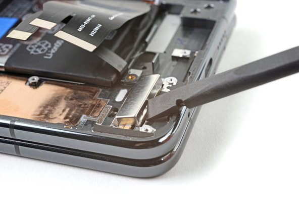
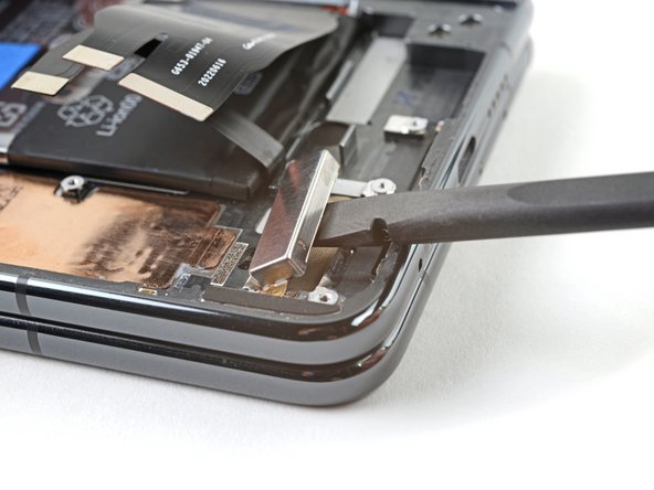
- Insert the flat end of a spudger between the bottom of the vibrator and the frame.
- Twist the spudger to create a gap.
- Push the flat end of the spudger into the gap.
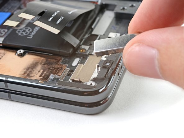
- Pry up and separate the base vibrator adhesive.
- Remove the base vibrator.
- During reassembly, if your adhesive is still intact and sticky, you can reuse it. Otherwise, follow this guide to replace the adhesive with custom cut strips.
- If you don't have custom cut adhesive strips, use double-sided tape, like Tesa Tape, to secure the vibrator to the frame.