Macbook Air M2 2022 Touch ID Sensor Replacement
ID: 162774
Description: Use this guide to replace the Touch ID...
Steps:
- Before you begin, discharge your battery below 25%, as a charged lithium-ion battery can be dangerous if accidentally punctured.
- Power off your MacBook Air and unplug all cables.
- Close the display and flip the laptop upside down. Keep the lid closed until you've physically disconnected the battery.
- Use a P5 Pentalobe driver to remove the four 6.4 mm screws securing the lower case:
- Two screws with a short threaded portion near the hinges
- Two screws with a long threaded portion near the front of the MacBook
- Throughout this repair, keep track of each screw and make sure it goes back exactly where it came from.
- Apply a suction handle to the center of the lower case's front edge.
- Pull up on the suction handle with strong, steady force to create a small gap between the lower case and the frame.
- Insert an opening pick into the gap.
- During the next two steps you'll feel and hear four snapping clips release. If a clip doesn't release, insert your opening pick farther and try again.
- Slide the pick to the bottom right corner to release the first clip.
- Slide the pick around the corner and up the right edge to release the next clip.
- Insert the opening pick in the original gap created with the suction handle.
- Slide the opening pick to the bottom left corner and up the left edge to release the two remaining snapping clips.
- Four sliding tabs along the back edge of the MacBook firmly secure the lower case. Separating these tabs requires a lot of force—consider using gloves to protect your hands from the sharp edges of the lower case.
- Keep the lower case flat and firmly pull it straight away from the back edge, one corner at a time, to disengage the sliding tabs.
- Don't pull up until the cover is completely separated.
- Remove the lower case.
- During reassembly:
- Set the lower case in place and align the sliding tabs with the screw heads they slide over. Press down and slide the lower case toward the back edge to engage the tabs—it'll stop sliding as the tabs engage.
- When one side is engaged, it may push the other out of alignment. Check both sides as you push, there should be no gap along the back edge.
- Once the lower case is flush with the frame, press down firmly along the perimeter to engage the four snapping clips.
- You'll hear and feel a distinct click as each clip snaps into place.
- Use a T3 Torx driver to remove the two 1.5 mm screws securing the battery connector cover.
- Remove the battery connector cover.
- Use an opening pick to pry up and disconnect the battery press connector.
- To reconnect a press connector, align it over the socket and gently press down on one side until it clicks into place, then press down on the other side. It might take a few tries to align the connector.
- Use a T3 Torx driver to remove the two 1.5 mm screws securing the trackpad cable cover.
- Use a spudger or your fingers to move the trackpad cable cover out of the way so you can access the press connector underneath.
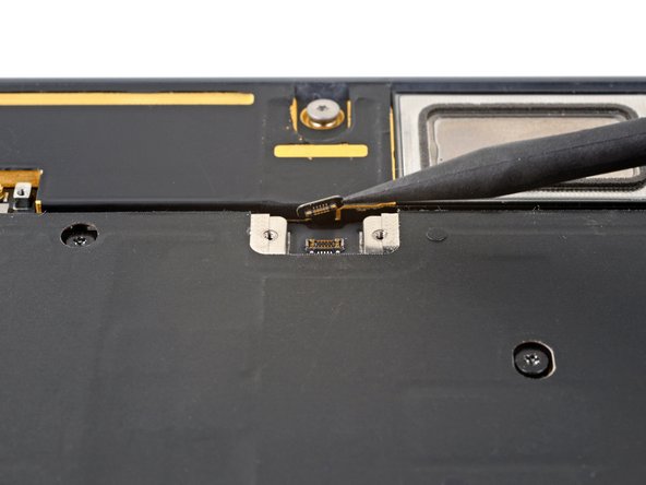
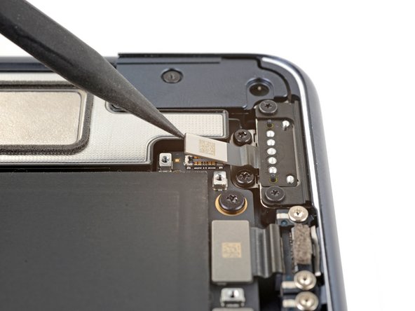
- Use the pointed end of a spudger to pry up and disconnect the trackpad cable press connector.
- To re-attach press connectors like this one, carefully align and press down on one side until it clicks into place, then repeat on the other side. Do not press down in the middle. If the connector is misaligned, the pins can bend and cause permanent damage.
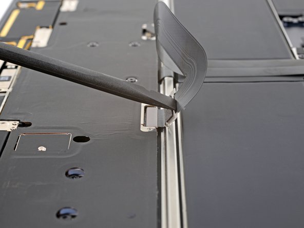
- Peel up and remove the foam pad from the lower display cable cover to reveal a hidden screw.
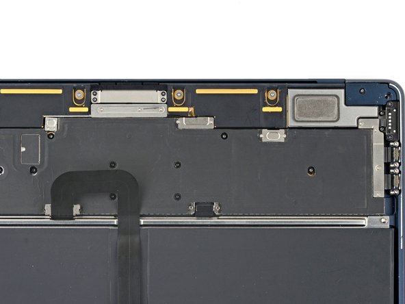
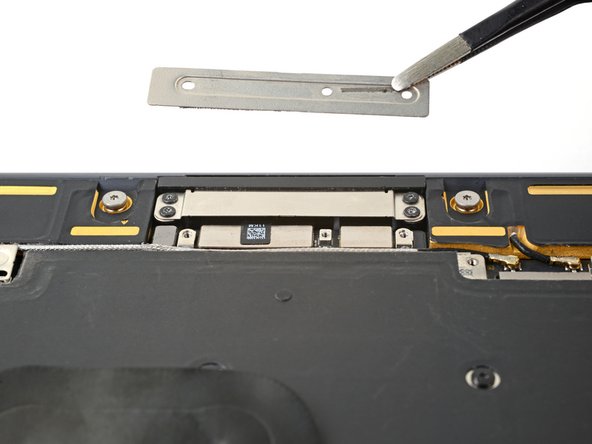
- Use a T3 Torx driver to remove the fourteen 1.5 mm screws securing the various cable covers.
- Use tweezers or your fingers to remove the six cable covers.
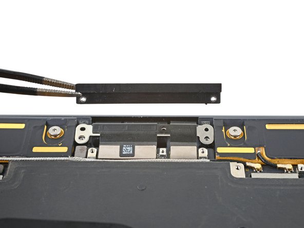
- Remove the four screws securing the upper display cable cover:
- Two 2.5 mm P2 Pentalobe screws
- Two 2.5 mm 3IP Torx Plus screws
- During reassembly, the Pentalobe screws must thread into their holes on the plastic securing bracket.
- Remove the upper display cable cover and plastic securing bracket.
- During reassembly, make sure that the upper lip of the metal cable cover slots into the plastic bracket.
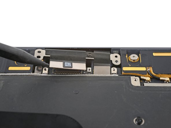
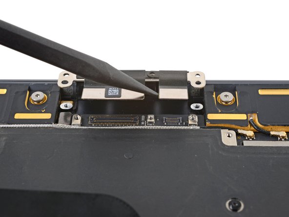
- Use the pointed end of a spudger to pry up and disconnect both display cable press connectors.
- Disconnect the microphone array press connector, directly to the left of the display cable.
- Disconnect the left and right speaker press connectors.
- Insert the flat end of a spudger between the the interconnect cable and the screw post.
- Pry up and disconnect the interconnect cable.
- Disconnect the MagSafe port press connector.
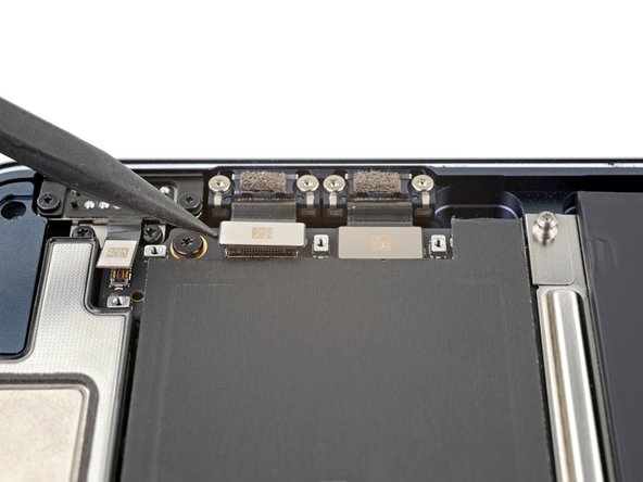
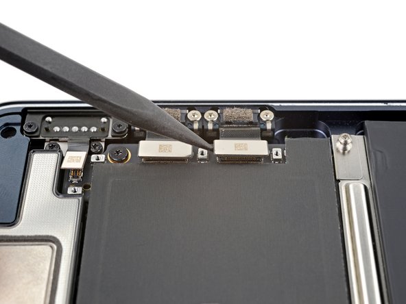
- Disconnect both Thunderbolt port press connectors.
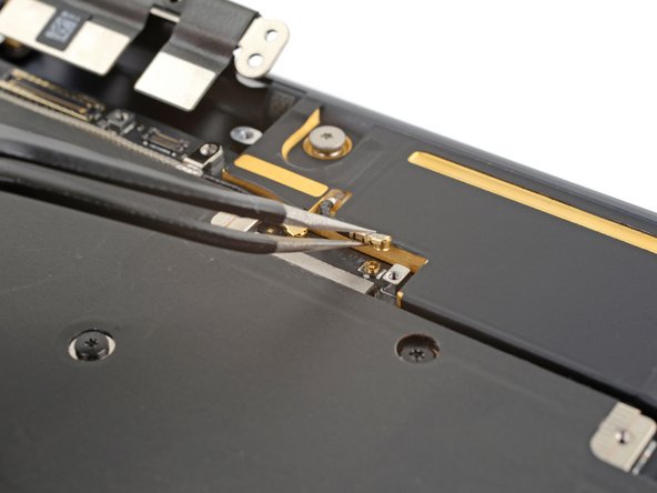
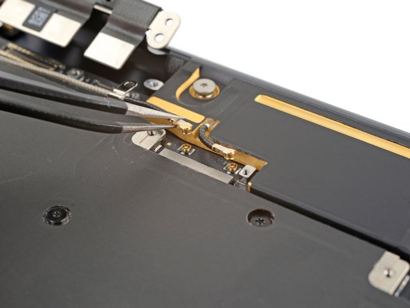
- Use a pair of tweezers to grip the first antenna connector, as close to its base as possible.
- Lift straight up to disconnect the cable.
- The antenna connectors on the logic board are very fragile. When disconnecting the cables, pull straight up—don’t bend them to the side.
- Repeat for the second antenna cable.
- To reattach antenna connectors like these, align the connector over its socket and press down with the flat end of a spudger. The connector should snap into place. This can be tricky and may take a few tries.
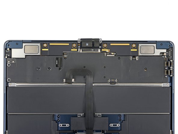
- Remove the nine screws securing the logic board:
- Three 3.8 mm T5 Torx screws
- One 3.6 mm T5 Torx screw
- Two 3.4 mm T5 Torx screws
- One 3.1 mm T5 Torx screw
- Two 2.7 mm 3IP Torx Plus screws
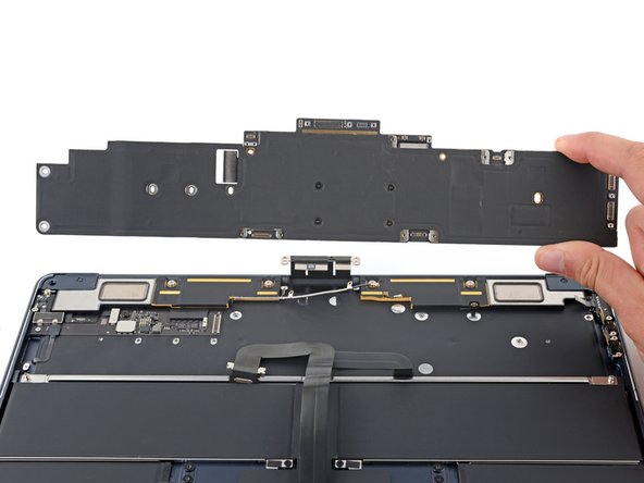
- The logic board and its cover are connected and remove as one assembly.
- The cover extends out from the logic board's left edge and bends easily. Don't pull the board up from this side.
- Grip the right side of the logic board and slide it towards the trackpad until it clears the overhangs near the speakers.
- Remove the logic board.
- When you reinstall the logic board, verify that no cables get trapped under the board as you lower it into place. Check each of the seven locations carefully:
- Right speaker cable
- Trackpad cable
- Display cables and microphone array cable
- Antenna cables
- Battery cable
- Left speaker cable
- USB-C and MagSafe cables
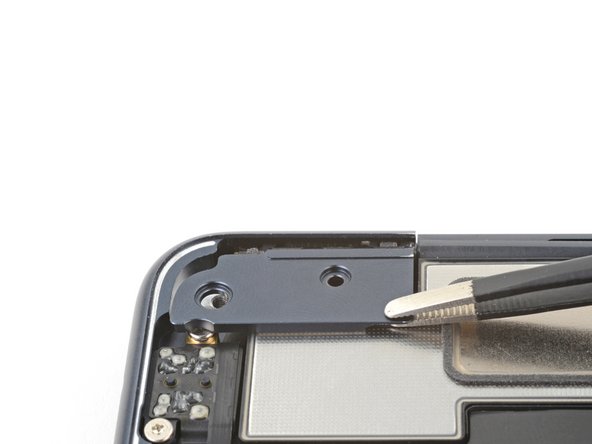
- Use a 3IP Torx Plus driver to remove the 2.6 mm screw securing the left hinge cover.
- Grip the left hinge cover with blunt nose tweezers.
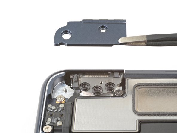
- Pull the cover toward the bottom of the laptop and upward to free it from its recess.
- Pull up and remove the hinge cover.
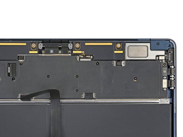
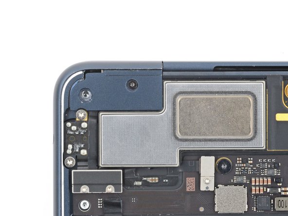
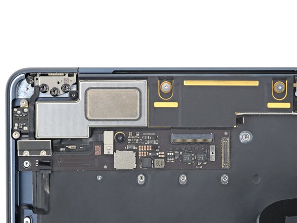
- The right speaker will be on your left-hand side when working on the MacBook, as it's laying upside down.
- Remove the three screws securing the right speaker:
- Two 5.6 mm 4IP Torx Plus screws
- One 3.5 mm T5 Torx screw
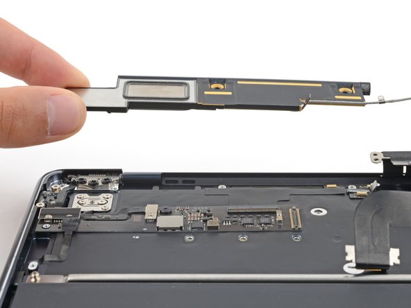
- Lift the right speaker straight up and remove it.
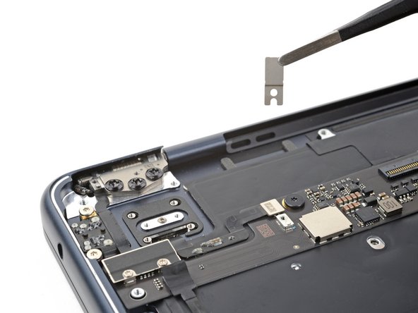
- Use a T3 Torx screwdriver to remove the 1.5 mm‑long screw securing the Touch ID sensor connector cover.
- Remove the cover.
- Use a T3 Torx screwdriver to remove the six screws securing the Touch ID sensor and its bracket:
- Four 2.0 mm screws
- Two 1.7 mm screws
- Remove the Touch ID sensor bracket.
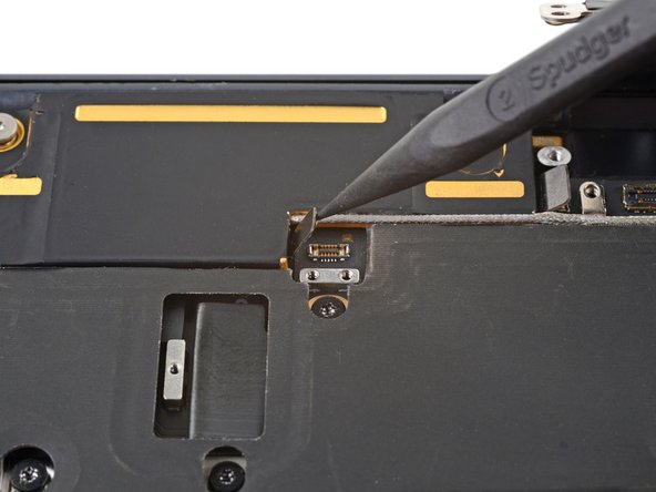
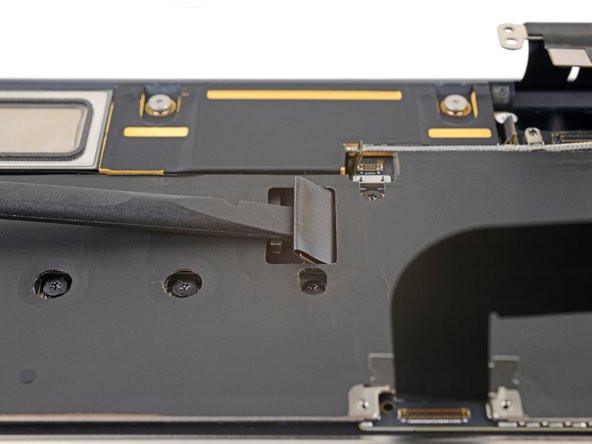
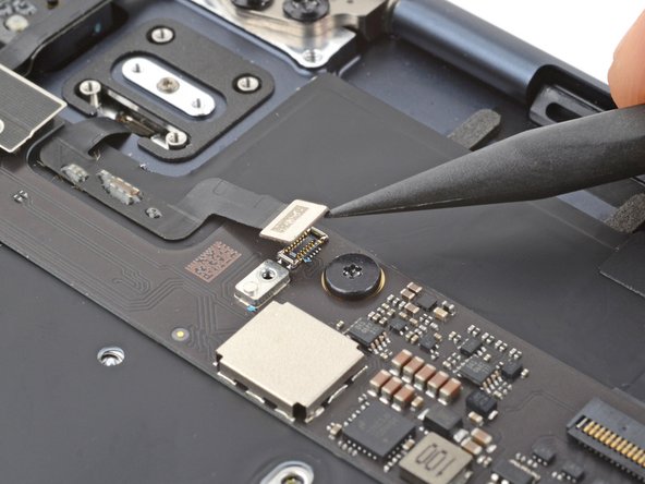
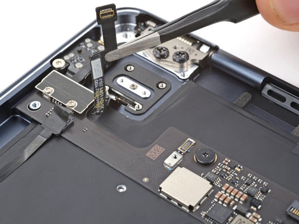
- Use a spudger to pry up and disconnect the Touch ID sensor press connector from the daughterboard.
- Light adhesive secures the Touch ID sensor cable to the frame.
- Use tweezers or your fingers to peel the Touch ID sensor cable from the frame.
- During reassembly:
- If your new Touch ID sensor's cable comes with adhesive, remove the plastic liner and press the cable into place on the frame.
- If the cable doesn't have adhesive, use a strip of double-sided tape such as Tesa Tape to secure it to the frame.
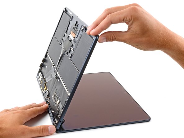
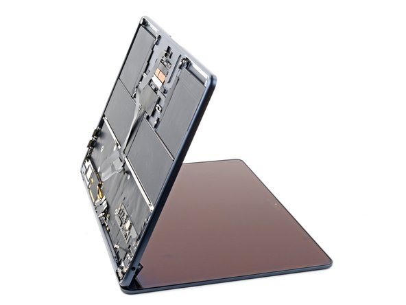
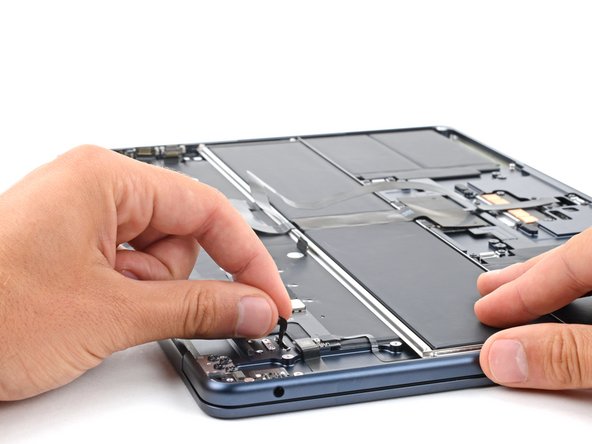
- Open your MacBook until the main body stands up on its own.
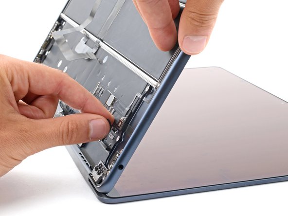
- Pull the Touch ID sensor away from the frame while guiding the cable through its slot.
- Remove the sensor.
- During reassembly:
- Guide the new Touch ID sensor's cable through its slot in the fame.
- Make sure the cable is properly oriented so the press connector lines up with its socket.
- Hold the cable with one hand and use your other hand to align the new sensor in its recess.
- Once the sensor is aligned, gently pull the cable away from the MacBook to secure the sensor against the frame.
- Continue holding the sensor in place by its cable and slowly close the MacBook.