Step-by-Step Installation of MANTRA ALISIO MINI cooling fan model.
ID: 163042
Description:
Steps:
- MANTRA ALISIO MINI cooling fan, step-by-step explanation of the check before installation, teardown of the luminaire being replaced, and assembly of the cooling fan.
- Unboxing and checking the contents of the box.
- We will check that all the LED board parts appear to be in good condition. The manufacturer performs the corresponding quality control checks, but as a buyer, it is your right and duty to inspect it. Remember that in the event of a defect, we must return the entire unit to the store with the original packaging and plastic wrapping; without the box, there is no return.
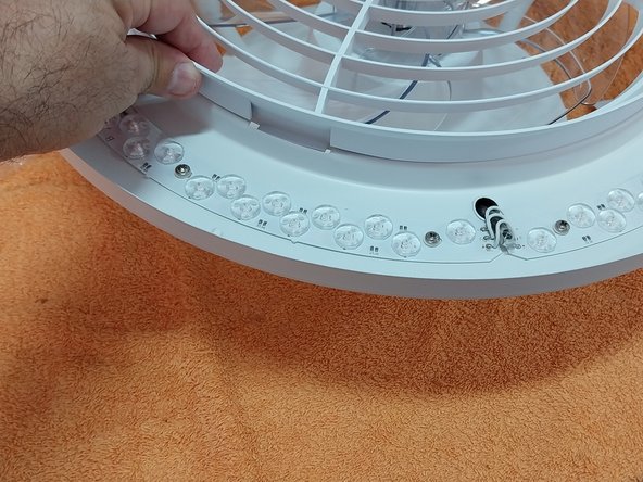
- During the review, we can observe the infrared LED that will detect the remote control signal; if we only install one cooling fan, it does not matter where we place it, preferably as close as possible to the area from where we point the remote.
- In the case of installing 2 cooling fans, as is my case as you will see at the end of the document in step 30, we must install them, keeping in mind to place the infrared sensors as far apart as possible so that both cooling fans do not activate when pointing at one of them; in any case, it is praiseworthy of the manufacturer
- That the infrared sensor has a wide detection angle.
- Quick-connect terminal, with 90° movable lever; a pleasant surprise and a great quality detail that the manufacturer uses this type of simple, fast, and comfortable connection terminal instead of using screw terminal blocks (which are cheaper and more inconvenient to handle when connecting the device to the ceiling).
- DEVICE FUNCTIONALITY TEST:
- We assume the device is working correctly, but since it is a ceiling-mounted unit, it is worth checking its functionality comfortably on the table before being surprised that it doesn't work after completing all the mounting work.
- We will use a power cord that we might have at home and scissors to strip the end of the cable.
- We will connect Brown to Brown or Black and Blue to Blue; for this test, the ground connection (yellow wire) is not necessary, but if we have a cord with a ground connection, it is better if we also test that.
- View of the cables inserted and secured in the QUICK CONNECTION STRIP.
- We will install the batteries in the remote control.
- Power on the device and as soon as it is plugged into the power outlet, the lamp should turn on.
- Proceed to testing.
- Next, we will test all the remote control functions: dimming the light, turning it on and off, turning the cooling fan on and off, speed settings, etc.
- Once you have verified that everything is working correctly, disconnect the test cable and disassemble the grille by rotating it until the notch aligns with the opening.
- Remove the propeller. The knob indicates which position locks it and which position unscrews it. As with all cooling fans, the thread is reversed so that it tends to tighten when spinning, therefore, by turning clockwise, we remove the knob.
- Remove the propeller.
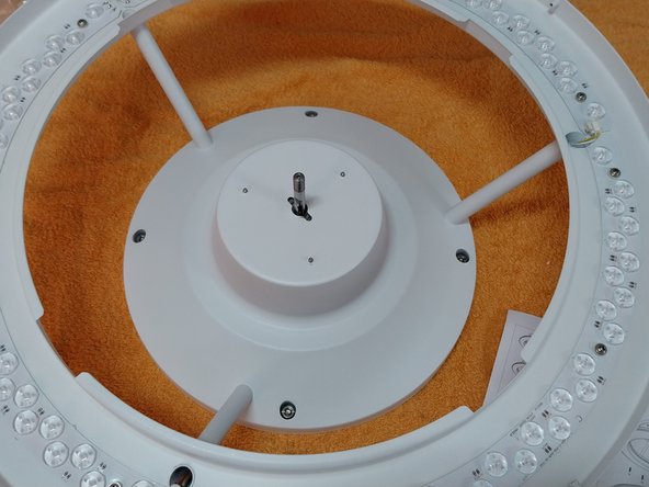
- Once the propeller is removed, we now have access to the 4 screws that secure the D-Pad that anchors the cooling fan to the ceiling.
- Unscrew the 4 screws using a flat-head screwdriver.
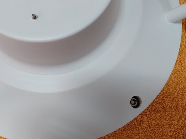
- Verify that the connector lays flat and fits perfectly into the opening.
- Remove the D-Pad.
- Now it is time to disassemble the light fixture you are going to replace; steps 16 to 19 are for guidance only, as they will vary depending on the light fixture you have installed.
- With the light fixture turned off AND PREFERABLY WITH THE LIGHTING CIRCUIT BREAKER DISCONNECTED AT THE ELECTRICAL FRAME.
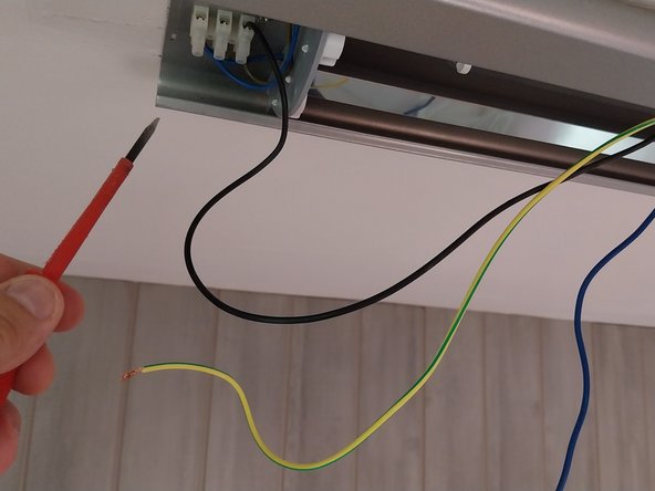
- Remove the 3 wires: Black - Phase, Blue - Neutral, Yellow - Ground TT.
- As an added safety measure, or if we have not disconnected the circuit breaker from the electrical frame, tape the ends of the 3 wires before removing them from the light fixture being disassembled.
- Disconnect the cables and finish removing the screws from the light fixture.
- Take measurements to center the D-Pad in the space available on the ceiling, keeping in mind that the ceiling hole must be covered.
- Using a PENCIL, mark the 4 holes centered in the gap; if you deviate slightly while drilling, the D-Pad allows for slight lateral adjustment.
- Why do we use a PENCIL? The reason is simple: if you use a pen or marker and accidentally make a mark on the ceiling, it cannot be removed, let alone painted over—the mark will always show through. NEVER USE MARKERS ON CEILINGS OR WALLS.
- Pencil marks can always be removed with an eraser or a damp cloth.
- Screws and wall plugs: the manufacturer includes fairly high-quality screws of an appropriate length.
- The white plastic wall plugs serve their purpose, but I personally always prefer to use FISCHER wall plugs, which have a contour, are much more ribbed, and offer better grip and quality.
- In this case, rather than the 6 mm wall plugs I use for almost everything because it is a very suitable standard size, they will not be the right size. Instead, I am using 8 mm wall plugs, which are better suited to the screw provided by the manufacturer.
- To drill the hole in the ceiling, I recommend using a vacuum cleaner along with a drill with an 8 mm masonry drill bit. It is not shown in the photo, as it was impossible to hold the drill, the vacuum cleaner, and the phone for the photo all at the same time.
- The manufacturer does not include them, but as a personal tip, to avoid vibrations, I place some felt pads (for furniture) on the D-Pad, which absorb vibrations between the cooling fan and the ceiling.
- In this case, I am placing 5 round pads.
- Screwing the D-Pad to the ceiling.
- A check before making the connections.
- If you have a voltage tester or a test pen, make sure that the Phase corresponds to the black wire.
- Connect the circuit breaker and the switch, and verify that the phase is reaching us through the black wire.
- Why do we perform this check?
- Because electronics manufacturers indicate in their specifications where to connect PHASE or LINE and Neutral or N, as it is not recommended for some devices to have the phase and neutral reversed for proper operation, since some electronic equipment may not synchronize properly.
- In this case, it is correct: Phase is on the black wire, which is cut when the switch is activated.
- With the power disconnected again, we will connect the 3 cables to the QUICK-CONNECT TERMINAL BLOCK.
- Of the entire assembly, this is the most complicated part, as you have to align the screws of the D-Pad with the 4 holes of the cooling fan, ensure the connection terminal is in the recess, hold the cooling fan to the ceiling, and proceed to screw in the 4 fasteners.
- Photo 3: before continuing, we will check if the lamp turns on.
- We will install the propeller and the knob.
- We install the outer diffuser ring.
- And finally, we snap the grille into place by aligning the notches.
- View of one of the 4 side notches.
- Cooling fan installed.
- As a final step, we place the 4 screw hole cover caps. Although this step is performed much more comfortably if we do it before installing the propeller and the grille.
- Final appearance of the installed cooling fan.
- Once the first one is installed, I proceed to install the second one, which is much faster now after the experience gained from installing the first one.
- Final appearance.
- A highly recommended LAMP + cooling fan, and I advise you of one very important detail: when installed in a kitchen as in this case, the grille, the fan blade, and the diffuser are very easily removable for cleaning.