Nokia G310 5G Charging Port Assembly Replacement
ID: 163058
Description: Use this guide to replace the charging port...
Steps:
- Power down your phone and unplug any cables.
- Insert a SIM eject tool, bit, or a straightened paper clip into the small hole on the SIM card tray on the upper left edge of the phone.
- Press firmly to eject the tray.
- Remove the SIM card tray.
- When installing either a SIM card or a microSD card, make sure they're in the correct orientation and sitting completely flush with the edges of the tray before reinserting the tray into the phone.
- The back cover is held in place by plastic clips.
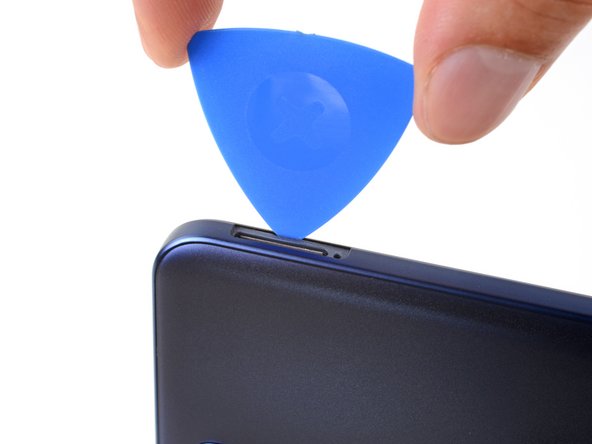
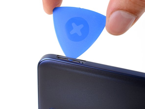
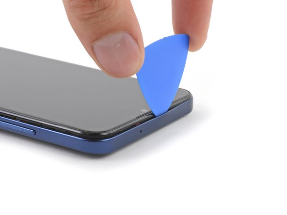
- Insert an opening pick under the small notch in the SIM card tray slot.
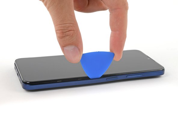
- Position the opening pick at a steep downward angle between the back cover and the screen assembly.
- Slide the opening pick down the left edge of the phone to release the plastic clips.
- Turn the opening pick around the corner and continue to slide it along the bottom edge to release the plastic clips.
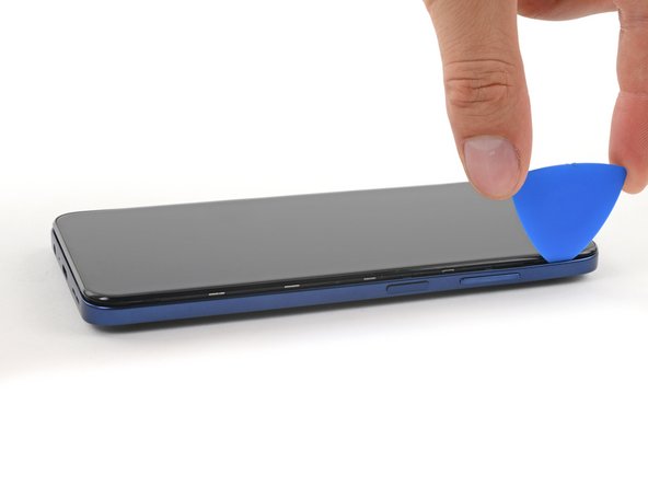
- Slide the opening pick up the right edge to continue releasing the plastic clips.
- Slide the opening pick along the top edge to release the remaining plastic clips.
- Don't try to fully remove the back cover just yet, as it's still connected with a cable.
- With the phone laying screen-side down, carefully lift the right edge of the back cover, opening it like a book.
- Take care not to strain or tear the attached fingerprint reader cable during this procedure.
- Lay the back cover next to the phone.
- Use a Phillips screwdriver to remove the 3.8 mm‑long screw securing the fingerprint reader bracket.
- Use a pair of tweezers or your fingers to remove the fingerprint reader bracket.
- Take care not to puncture the battery with sharp tools—a punctured or creased battery may leak dangerous chemicals or cause a fire.
- During reassembly, make sure to slide the bracket's edge back into its slot under the motherboard cover.
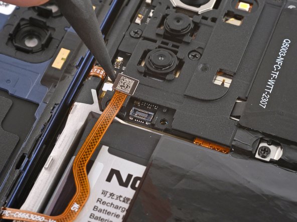
- Use the pointed end of a spudger to disconnect the fingerprint reader by prying the connector straight up from its socket.
- To re-attach press connectors like this one, carefully align and press down on one side until it clicks into place, then repeat on the other side. Don't press down on the middle. If the connector is misaligned, the pins can bend and cause permanent damage.
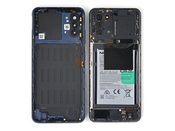
- Remove the back cover.
- A white sticker might cover one of the top screws. Pierce through it with the tip of your screwdriver or use a pair of tweezers to remove it.
- Use a Phillips screwdriver to remove the ten 3.8 mm-long screws securing the motherboard cover.
- The motherboard cover is further held in place by plastic clips.
- Insert an opening pick under the right edge of the motherboard cover.
- Twist the opening pick to release the plastic clips.
- During reassembly, clip in the motherboard cover on the top left first.
- Use a pair of tweezers or your fingers to remove the motherboard cover.
- Use the flat end of a spudger to disconnect the battery cable by prying the connector straight up from its socket.
- A white sticker might cover one of the top screws. Pierce through it with the tip of your screwdriver or use a pair of tweezers to remove it.
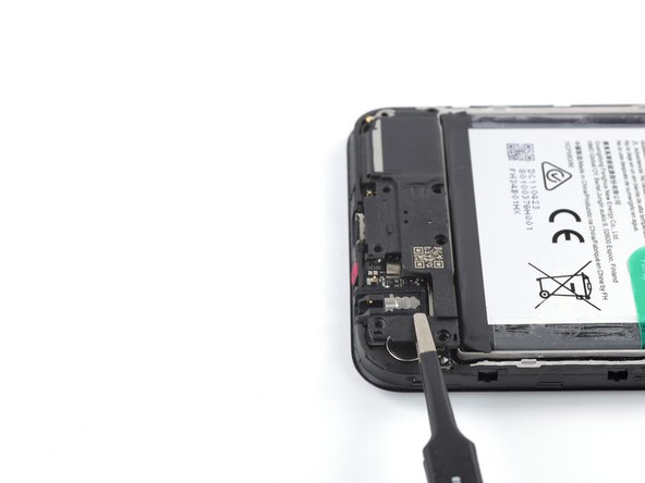
- Use a Phillips screwdriver to remove the eight 3.8 mm-long screws securing the loudspeaker.
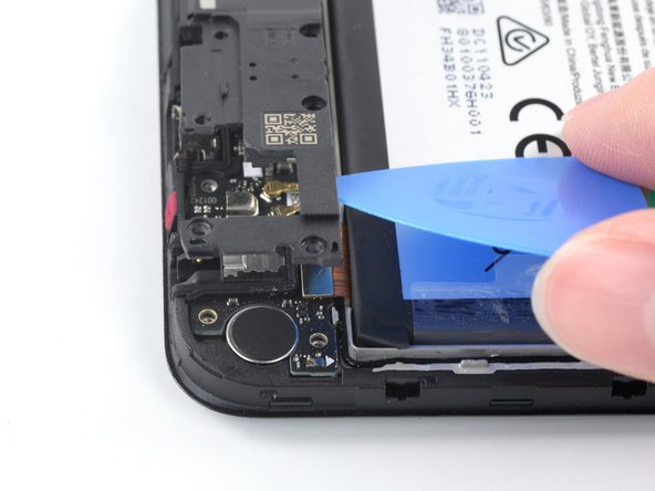
- Insert an opening pick underneath the top right edge of the loudspeaker.
- Avoid pushing down at a sharp angle, or you risk damaging the interconnect ribbon cable underneath.
- Twist the opening pick to release loudspeaker from the plastic clips holding it in place.
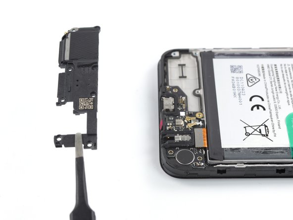
- Use a pair of tweezers or your fingers to remove the loudspeaker.
- Use the flat end of a spudger to disconnect the interconnect cable by prying the connector straight up from its socket.
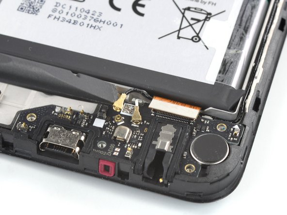
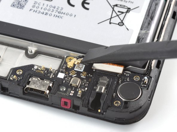
- Use a spudger to disconnect the antenna cables by prying their coaxial connectors straight up from the sockets on the board.
- Use a pair of tweezers or your fingers to grip the antenna cables near the connectors.
- Reposition the antenna cables out of the way of the charging port assembly.
- The top edge of the charging port assembly is held in place with adhesive.
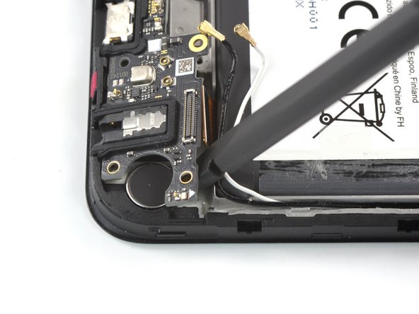
- Insert the flat end of a spudger underneath the top right edge of the charging port assembly.
- Pivot the charging port assembly up until you can grip it with your fingers.
- Use your fingers or a pair of tweezers to remove the charging port assembly.
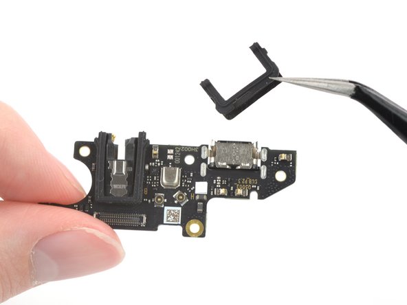
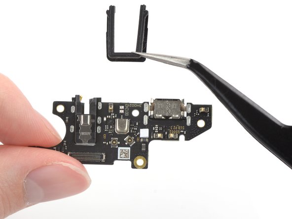
- Use a pair of tweezers to remove the two black U-shaped rubber gaskets from the charging port and the headphone jack.
- Only the charging port assembly remains.
- During reassembly, transfer the rubber gaskets to the replacement board before securing it back into the frame.