Scuf Instinct Pro Triggers Replacement
ID: 163216
Description: Follow this guide to replace, change, or...
Steps:
- Unplug all cables from your controller before starting.
- Completely power off your controller.
- Due to the controller’s odd shape, it can be helpful to stabilize it as you work. To prevent damage, consider laying it on a soft surface like a cloth or towel.
- Magnets secure the faceplace to the midframe.
- Lift the top edge of the faceplate to release the magnets securing it.
- Remove the faceplate.
- Weak magnets and two clips along the bottom edge secure the battery cover to the controller.
- Slide the battery cover away from the controller to remove it.
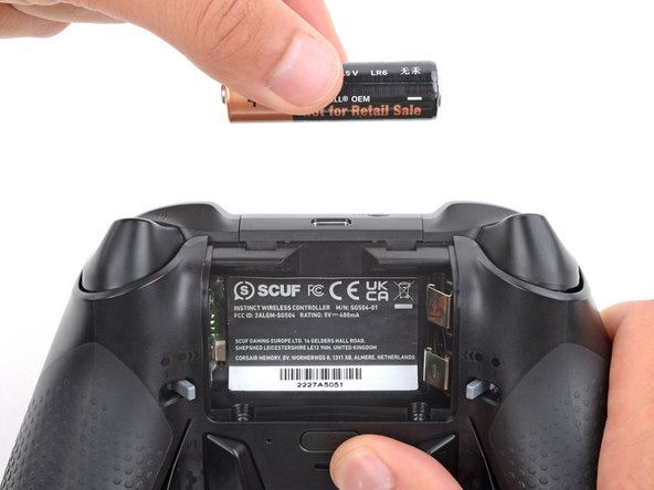
- If your batteries are starting to corrode, clean the contacts and replace the batteries.
- Use your fingers to remove the batteries.
- During reassembly, insert the batteries so their positive (+) and negative (–) ends match up with the markings on the battery contacts.
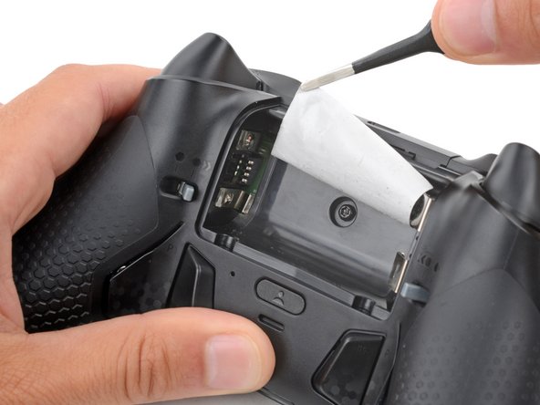
- The sticker in the battery recess hides a back cover screw.
- If you don't care about damaging the sticker, you can puncture through the center and skip the next step.
- Use a hair dryer to heat the sticker and soften the adhesive securing it.
- The sticker can be peeled without heating, but you risk tearing it.
- Use the point of a spudger to push up a corner of the sticker until you can grab it with a pair of blunt nose tweezers.
- Use your tweezers to peel up the sticker until the back cover screw is accessible.
- Throughout this repair, keep track of each screw and make sure it goes back exactly where it came from.
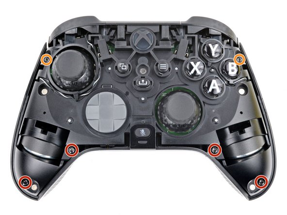
- Use a T8 Torx screwdriver to remove five 9.3 mm‑long screws securing the midframe:
- One back cover screw
- Four screws on top of the midframe
- Use a T6 Torx screwdriver to remove the two 9.3 mm‑long screws securing the midframe.
- Plastic clips secure the bottom edge of the midframe.
- Insert the flat end of a spudger between the bottom edge of the midframe and back cover.
- Pry the midframe up with the spudger to release the clips.
- Continue prying along the bottom edge to release the remaining clips.
- Don't try to remove the midframe from the back cover yet—a delicate ribbon cable connects them.
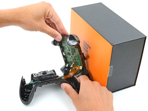
- Put a box or a stack of books to the right of the controller so you can prop up the midframe while disconnecting its ribbon cable.
- Secure the back cover with one hand, and use your other hand to grip the midframe's left edge.
- Lift the midframe and rotate it over the right edge of the back cover, so the midframe's right edge is on your workspace.
- Prop the midframe up, being careful not to strain the ribbon cable.
- During reassembly:
- Guide the battery connectors on the midframe through their slot in the back cover.
- Make sure the contacts slide into their grooves in the battery recess. If they aren't in the correct spot, the controller won't receive power.
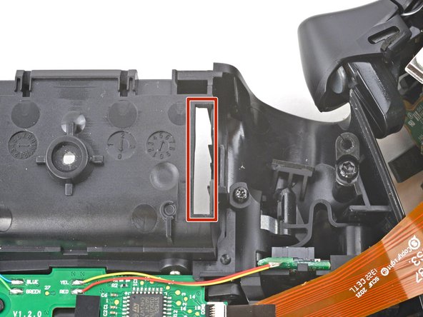
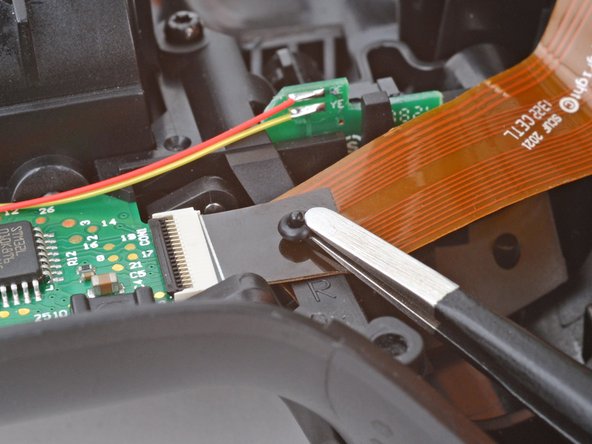
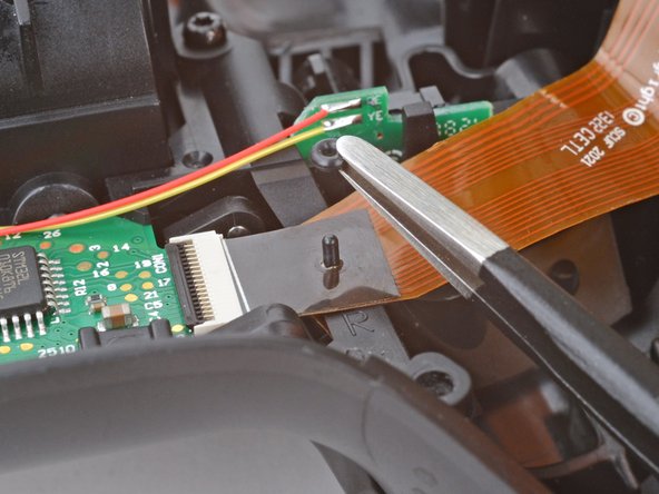
- A very small rubber grommet secures the midframe's ribbon cable to a post on the right side of the back cover.
- Use blunt nose tweezers to remove the grommet—don't lose it!
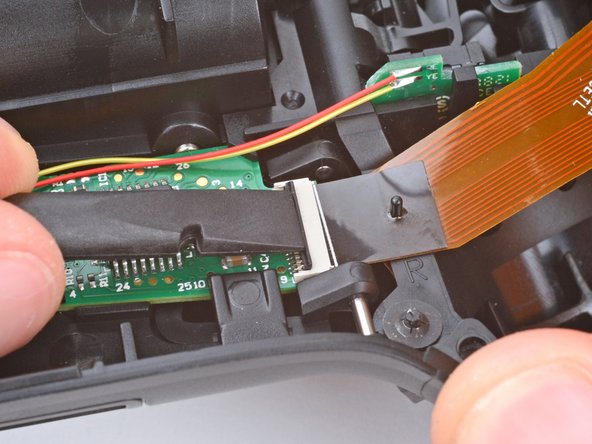
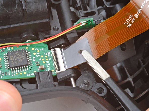
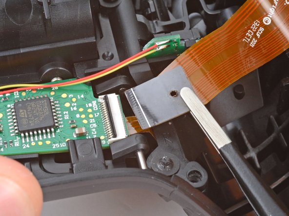
- Use the flat end of a spudger or a clean fingernail to lift the hinged locking flap on the midframe cable ZIF connector.
- Use blunt nose tweezers to grip the black pull tab on the midframe cable.
- Lift the midframe cable off its post and pull it straight out of its socket.
- Remove the midframe.
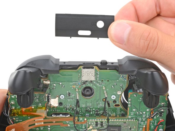
- The top of the USB‑C port cover is secured with a pair of plastic arms. The bottom is secured with plastic clips.
- Rotate the underside of the USB‑C port cover up and away from the controller to release the bottom clips.
- Unhook the plastic arms and remove the cover.
- During reassembly:
- Hook the ends of the USB‑C cover's arms into their slots on either side of the Xbox button.
- Rotate the cover downward until the bottom clips engage and the cover is flush with the bumpers.
- Tight plastic clips secure the outer edges of the bumpers. Unclipping them requires some force.
- Insert the point of a spudger between the midframe and the inner edge of one of the clips.
- Pry the clip outward until it comes off its post and the bumper is freed.
- Use your fingers to rotate the other bumper away from the controller until the clip comes off its post.
- Remove the bumpers.
- During reassembly:
- Make sure the tabs on the midframe and bumpers go into their corresponding cutouts.
- Hook one of the bumpers onto its post and push the other bumper into the midframe until its clip snaps into place.
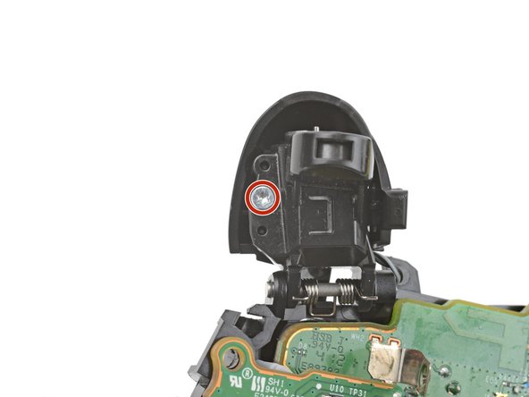
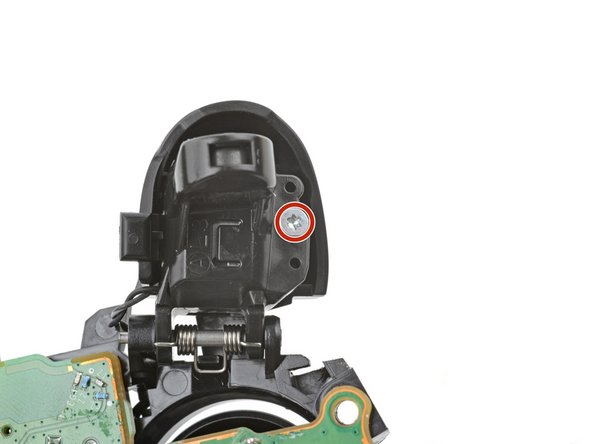
- Use a T6 Torx screwdriver to remove the 7 mm‑long screw securing each trigger (two total).
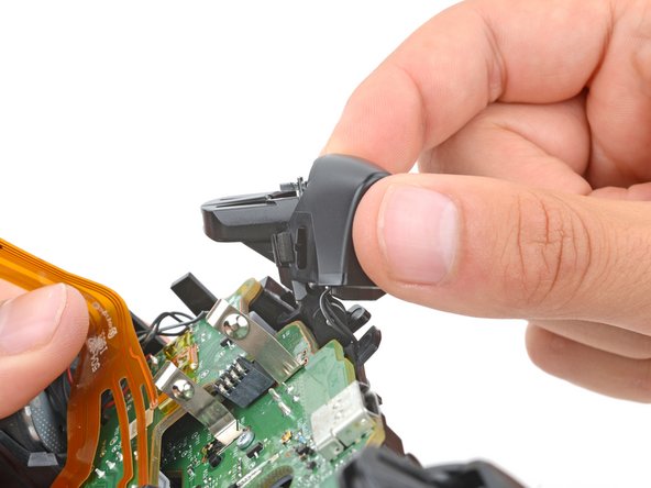
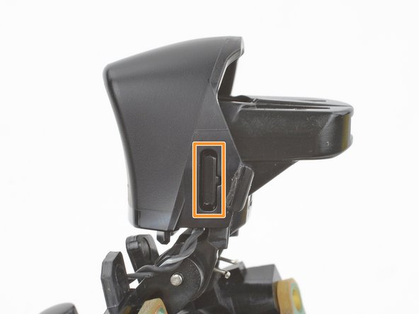
- A clip secures the inside edge of the trigger.
- Rotate the trigger toward the center of the controller to unclip it.
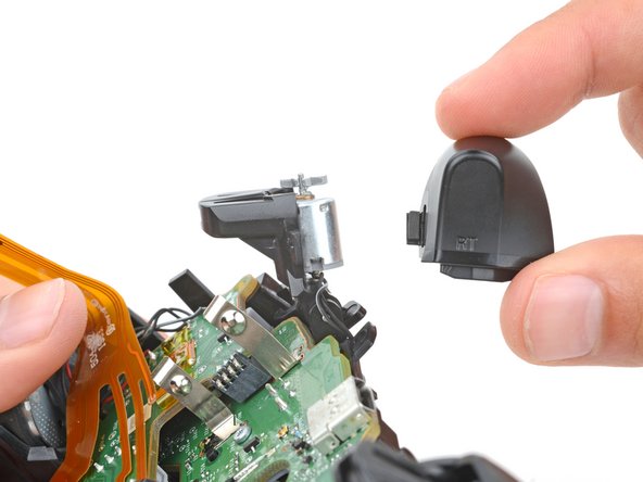
- Remove the trigger.
- Use the same process to remove the other trigger.
- During reassembly:
- Make sure the trigger rumble motors are correctly oriented (flat-side up) before installing a trigger.
- To install a trigger, hook the inside edge onto its post and push the trigger until it snaps into place.