HTC Vive XR Elite Hinges Replacement
ID: 163324
Description: Use this guide to replace one or both hinges in...
Steps:
- Before starting this repair, discharge the batteries in your headset below 25%. A charged battery may leak dangerous chemicals or catch fire if damaged.
- Playing Half Life: Alyx will do the trick!
- The Vive XR Elite has a proximity sensor that puts the headset in standby mode to save battery when it isn't in use. To drain the battery faster you'll need to use the headset.
- Disconnect the USB-C power cable.
- Press the release button on the right battery cradle temple slot.
- Pull the battery cradle away from the right temple slot to disconnect it.
- Repeat the previous step for the left temple slot.
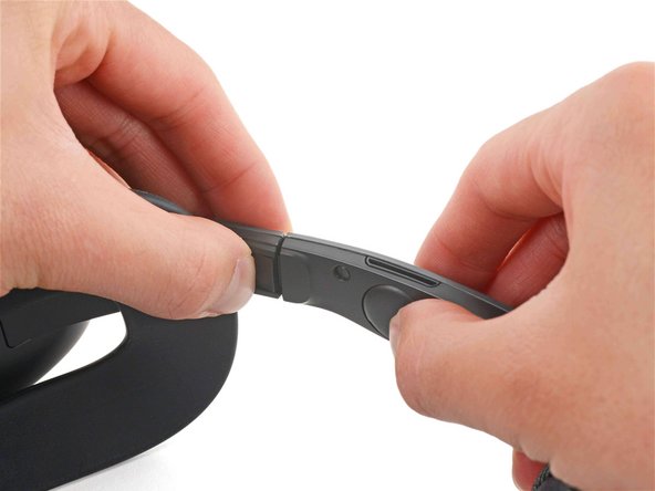
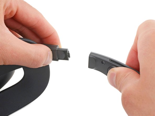
- Separate the headset and battery cradle.
- The face cushion is attached to the headset with two magnets. You'll feel the pull of the magnets as you remove it.
- Grip the middle of the face cushion with your fingers and pull back to remove it.
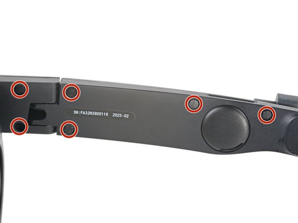
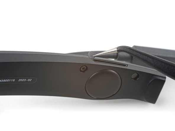
- Use tweezers to remove the six screw covers from the right temple.
- Use a T5 Torx screwdriver to remove the six 4.9 mm‑long screws securing the two right temple halves.
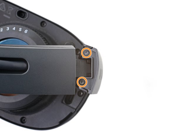
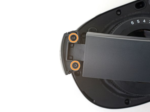
- Use a T5 Torx screwdriver to remove the two 3.5 mm‑long screws securing the right hinge cover.
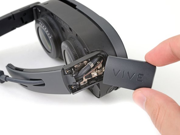
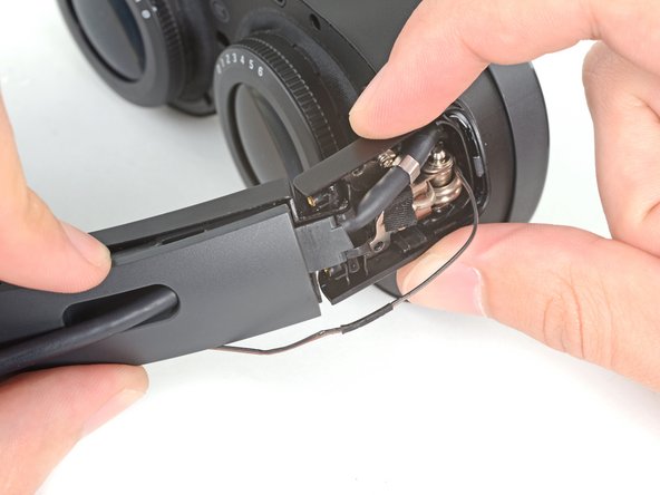
- Insert the flat end of a spudger in the gap between the right outer and inner hinge covers.
- Slide the spudger along the gap to separate the clips securing the outer hinge cover.
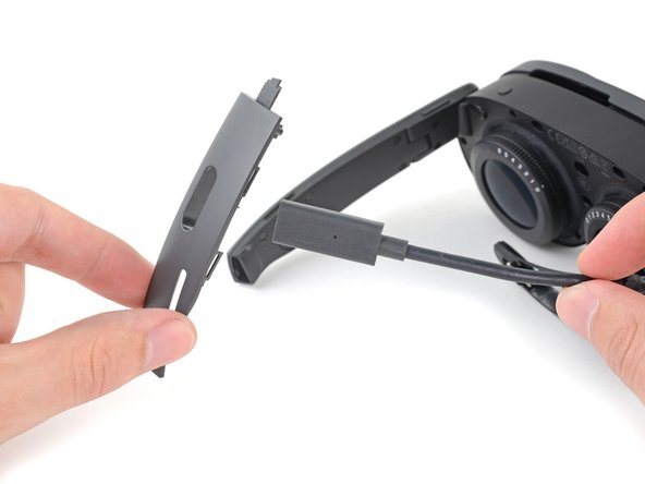
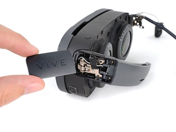
- Remove the outer hinge cover.
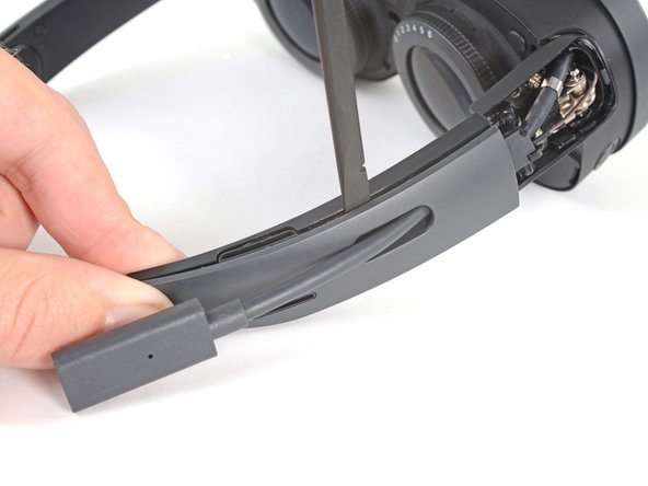
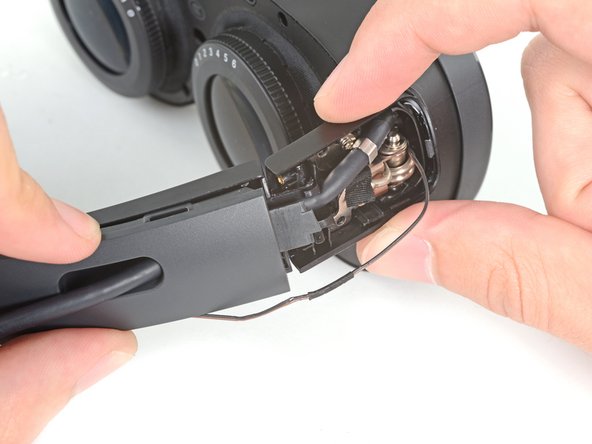
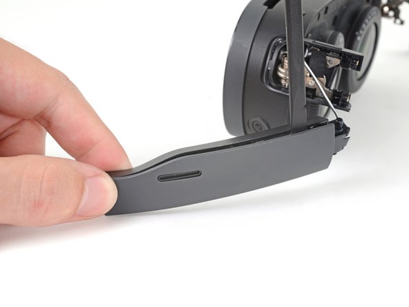
- Insert the flat end of a spudger in the gap between the outer and inner temple.
- Slide the spudger along the gap to separate the clips securing the outer temple.
- Slide the top of the outer temple out of its slot in the hinge.
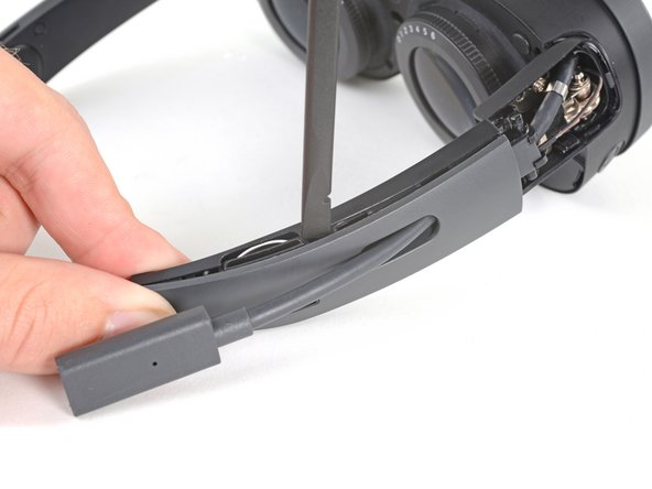
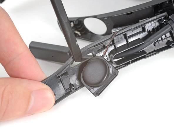
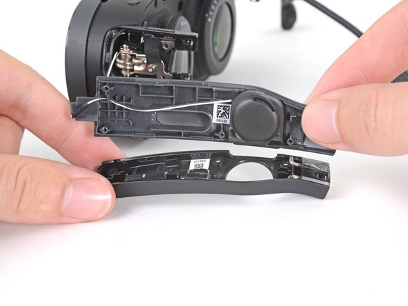
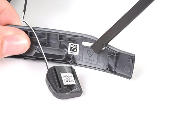
- The speaker is lightly adhered to the outer temple.
- Rotate the outer temple towards you to access the speaker.
- Slide the flat end of a spudger under the speaker to separate its adhesive.
- During reassembly, if your speaker adhesive isn't sticky, use double-sided tape to re-adhere the speaker to the outer temple.
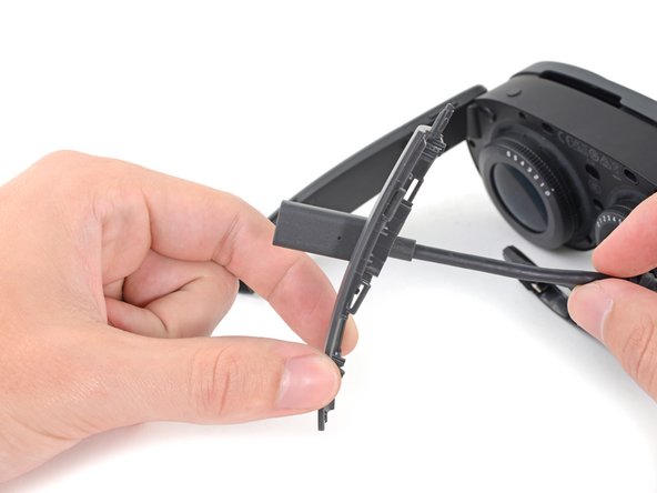
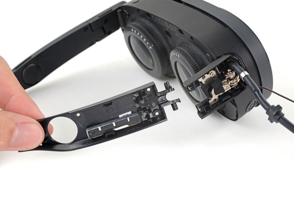
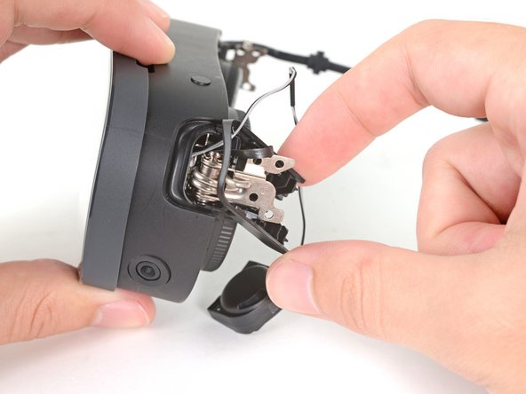
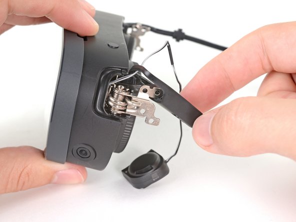
- Thread the outer temple off of the USB‑C cable and remove it.
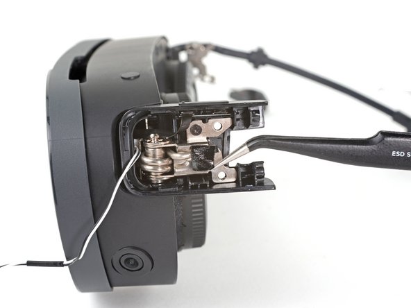
- Pull the inner temple out of its slot in the hinge and remove it.
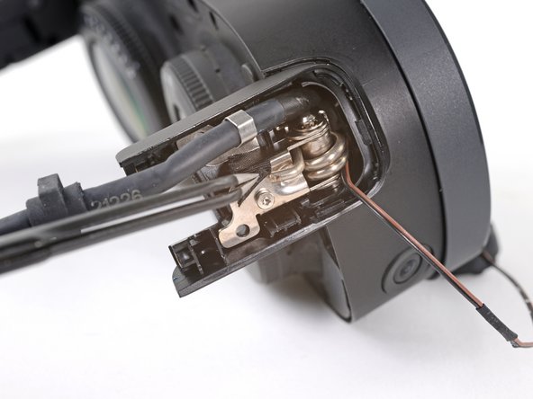
- Use tweezers to peel back the black tape covering one of the inner hinge cover screws.
- Use a T5 Torx screwdriver to remove the two screws securing the inner hinge cover:
- One 3.1 mm‑long screw
- One 4.9 mm‑long screw
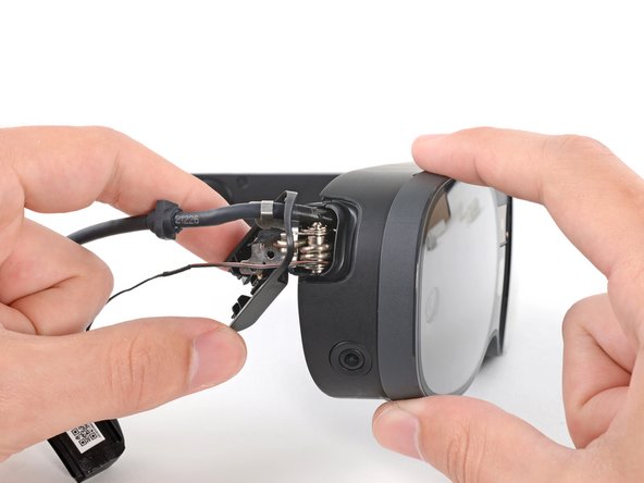
- Rotate the inner hinge cover off its groove in the frame.
- Thread the inner hinge cover off of the USB-C and speaker cables and remove it.
- Use tweezers to remove the six screw covers from the left temple.
- Use a T5 Torx screwdriver to remove the six 4.9 mm‑long screws securing the two left temple halves.
- Use a T5 Torx screwdriver to remove the two 3.5 mm‑long screws securing the left hinge cover.
- Insert the flat end of a spudger in the gap between the left outer and inner hinge covers.
- Slide the spudger along the gap to separate the clips securing the outer hinge cover.
- Remove the outer hinge cover.
- Pull the left temple out of its slot in the hinge.
- Don't try to fully remove it yet, as it's still connected by a cable.
- Insert the flat end of a spudger in the gap between the outer and inner temple.
- Slide the spudger along the gap to separate the plastic clips securing the outer temple.
- Pull the outer temple off of its inner half to completely release its plastic clips.
- The speaker is lightly adhered to the outer temple.
- Slide the flat end of a spudger under the speaker to separate its adhesive.
- Let the speaker rest next to the headset before continuing.
- During reassembly, if your speaker adhesive isn't sticky, use Tesa 61395 Tape to re-adhere the speaker to the outer temple.
- Use tweezers to peel back the black tape covering one of the inner hinge cover screws.
- Use a T5 Torx screwdriver to remove the two screws securing the inner hinge cover:
- One 3.5 mm‑long screw
- One 4.9 mm‑long screw
- Don't fully remove the inner hinge cover, as it's connected by the volume button cable.
- Rotate the inner hinge cover off its groove in the frame.
- Let the cover hang off its volume button cable for now.
- Use a T5 Torx screwdriver to remove the 12 screws securing the face plate:
- Six 3.5 mm‑long screws
- Four 4.9 mm‑long screws
- Two 6.5 mm‑long screws
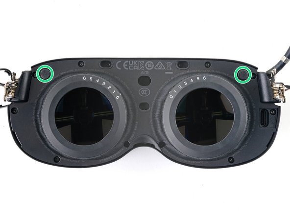
- There are two magnets at the top corners of the face plate. As you remove nearby screws, they might stick to them.
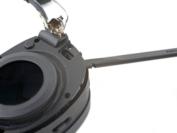
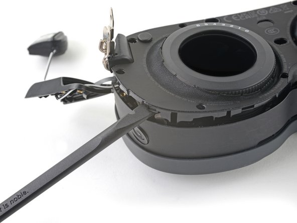
- Insert the flat end of the spudger in the gap between the frame and the bottom right corner of the face cover.
- Pry up with the spudger to release the clips securing the face cover.
- Repeat the prying process for the middle and bottom left portions of the face cover.
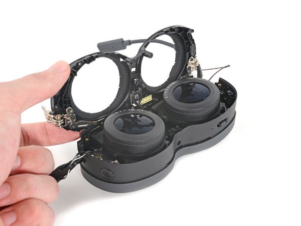
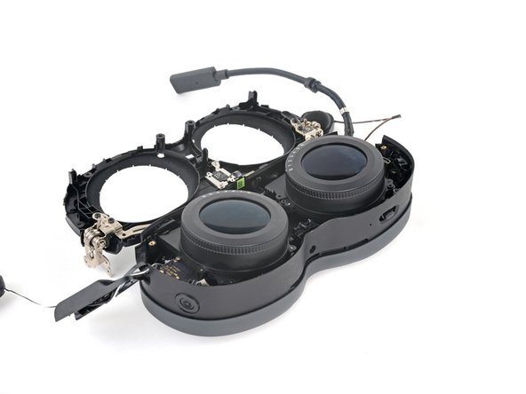
- Don't fully remove the face cover completely, as it's connected by the proximity sensor cable.
- Lift the face cover and rotate it over the top of the frame.
- Lay the face cover face up before continuing.
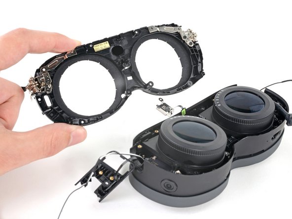
- Use a T5 Torx screwdriver to remove the two 3.3 mm‑long screws securing the proximity sensor cable.
- Remove the face cover.
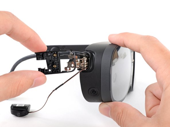
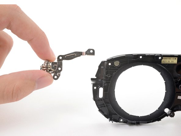
- Use a T5 Torx screwdriver to remove the four 4.7 mm‑long screws securing the hinges.
- Pull the hinges of their slots in the frame.
- You might feel some resistance, as there's a magnet sitting underneath it.