Troubleshooting DIY cable reels.
ID: 163371
Description: troubleshooting extension reels
Steps:
- Coil cables that do not output voltage, review and locate the problem, step by step.
- We will use a multimeter on the OHM scale, Beep = Continuity scale, to check:
- First we check if we have a short circuit between the 2 poles of the plug socket.
- We check if we have a derivation or connection with ground (Earth) of the socket base.
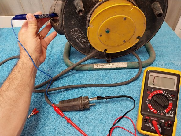
- To check the continuity of the 3 Phase – Neutral – Ground cables, we connect one tip of the multimeter to a pin on the plug socket and the other lead of the multimeter to the output plug socket.
- To make the checking task easier for you, since the terminals are very thick and the multimeter can give us more connections, I use an adapter or homemade tool.
- It's nothing more than a pen with a pin or thick tip for a plug. The truth is that it's great for this.
- Checking between input and output, we see that grounding and one of the punctures has continuity, the other cable does not have continuity, the multimeter does not perform measurement.
- Photos 1 and 2: Cable NOT OK open.
- Photo 3: Cable OK
- Detail of the 2nd cable of the plug socket, ok with continuity.
- If you are not clear about the continuity measurement, here it is explained with several different multimeters:
- https://www.youtube.com/watch?v=8hXeg-ne...
- Checked that we have a cut cable, we proceed to dismantle the plug base to check the state of the cables, the checks are nothing more than dismantling part by part and discounting possible problems.
- We open the socket by removing the side screw.
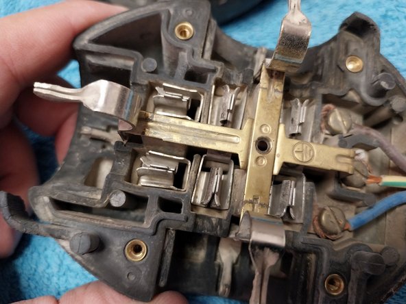
- Step 1, bend the cable, checking to see if any deformed parts are visible.
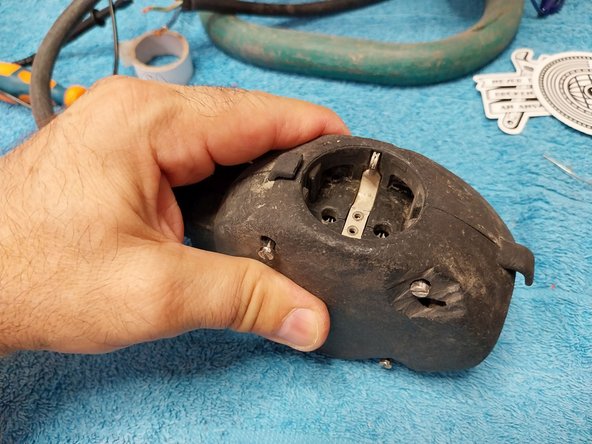
- 2. In this case we observe that the plug socket is broken, so we will proceed to replace it, but before doing so, we will carry out other checks.
- We remove the plug socket, which I replace in step 26.
- We spend an hour checking the condition of the plug base, we start already observing the electrical tape at the end, so it is not the first repair you have already suffered.
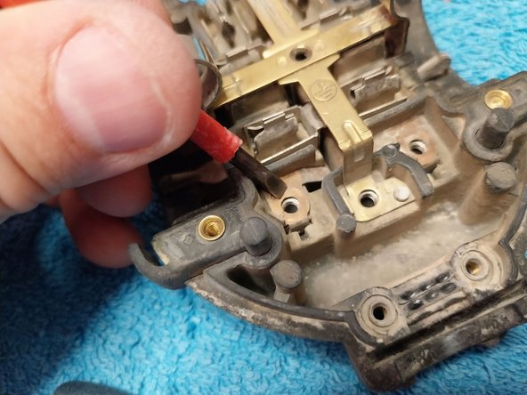
- In this case we dismantle it with a flat screwdriver.
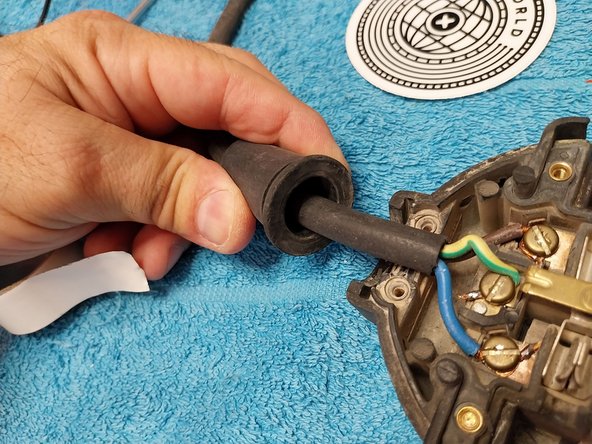
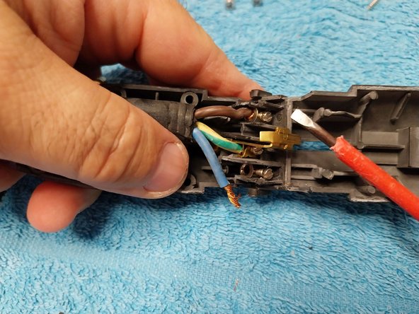
- Open the base, we see that it is of quite good quality, and that the interior is in apparent good condition, so we will focus on the cable, release the cable press.
- We will repeat the operation of step 4 and 5, this time to focus the problem on a specific cable.
- Photo 1: Blue Neutral OK
- Photo 2: Earth Taking, Yellow OK.
- Photo 3: Phase, Brown cable, NOK the multimeter does not measure on Ohms scale, cut cable.
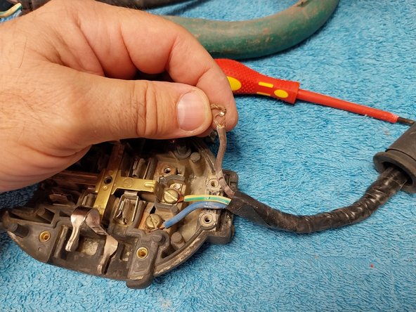
- Photo 1: We remove the screw that holds the cable.
- Photo 2: With the cable loose, we try to stretch it, the cables usually break in the next folds, when a cable breaks internally at the end it appears to be OK, but if we stretch it, we see that the plastic cover, it stretches like gum, until it breaks, LOCATED THE POINT WHERE THE FAILURE IS.
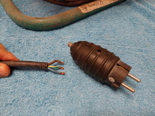
- Photos 1 and 2: We see how far the cable has broken.
- Photo 3: Since all this part of the cable has already had a previous repair and has electrical tape, I will proceed to remove it to start from a part of cable in good condition.
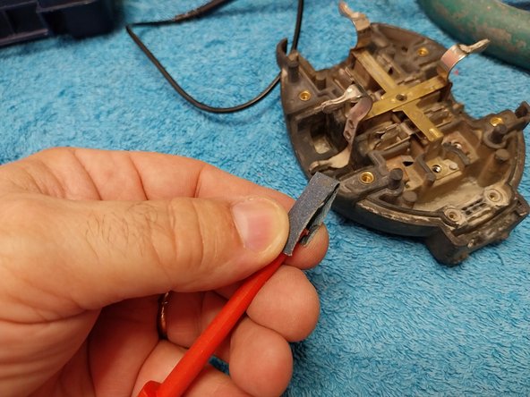
- I proceed to release the other 2 cables and since the connections are free, I take the opportunity to clean the electrical contacts with a piece of fine sandpaper, held at the tip of the screwdriver.
- Photo 1: The 3 clean "shiny" contacts
- Photos 2 and 3: We see that the remaining cable was really in bad condition, cracked.
- We cut the damaged piece and measure at the base to determine what portion of the rubber cover needs to be removed.
- Using the scissors, carefully make some light "bites" to peel off the rubber sheath. Once marked, stretch it.
- We peel 1 cm or a little more from the end of the 3 cables.
- Once the cable is stripped from approximately 1 cm to 1.3 cm, we separate the wires in half and half and braid them.
- We put the screw and braid the cable around it.
- The same for the 3 screws.
- So we can place them already in the socket base, but if we have an electronics and tin welder, it does not hurt and gives a very professional finish, applying a welding point at the end of the tram so that it does not come loose when pressing.
- We connect the 3 cables to the socket base.
- Now it is the turn of the rubber cover, it passes walls, the cable has a lot of slack inside the cover, so, to give it rigidity, we can give it a few turns of insulating tape, which add volume to the cable and prevent the entry of dirt into base.
- We place the wall-mounted walker.
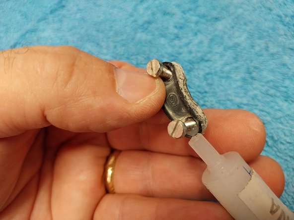
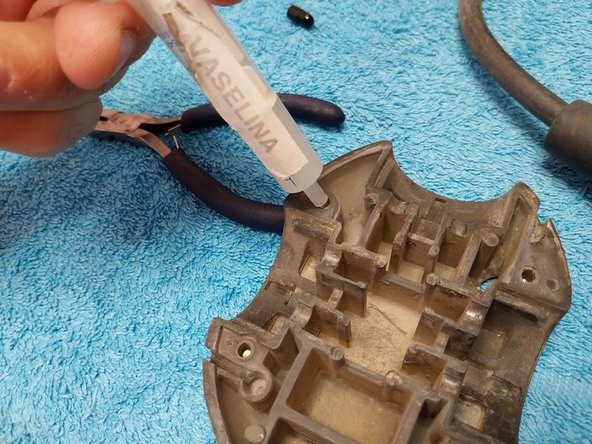
- We prepare the cable press to reposition it, in the holes we can apply a little petroleum jelly, which will make it easier for the screws to enter smoothly, and for future repairs to come out easily.
- At the base of the cable gland screws, if we apply a little Vaseline, they will adapt perfectly to the shape of the cable gland when tightening them.
- A little Vaseline on each of the 4 screws, so that they screw smoothly and we can close the 2 halves.
- Photo 1: We insert the 4 screws.
- Photo 2: We will check continuity between input and output of the 3 cables.
- Photo 3: We can proceed to assemble the plug socket
- To assemble the socket, we use the same methodology explained in other previous steps.
- Since it is a plug socket with a rubber cover, to assemble it more easily we can apply a little Vaseline so that the cover fits smoothly.
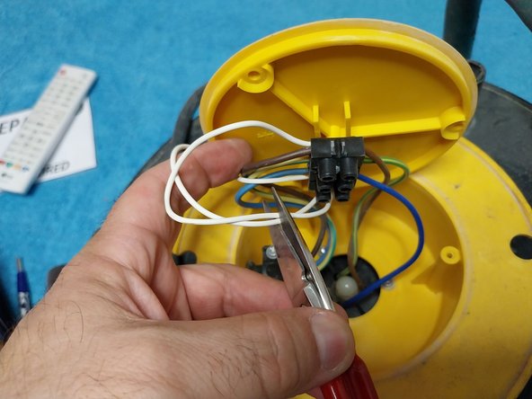
- Once this is done, it is time to check the neon lamp, which is also faulty. We remove the screws from the side cover.
- The lamp is not melted, but it is very deteriorated, it hardly emits light, so I proceed to replace it.
- Instead of replacing all the cable, since the cable of the new lamp is very fine, we join the new lamp, 2 pieces of white cable from the original lamp, since this cable is of greater diameter and quality.
- The spare lamp cables are welded to the 2 white cables of the original lamp, and are lined with insulating tape or retractable thermo tube, they can also be joined with electrician strips.
- Cable reel repair, indicator lamp working.