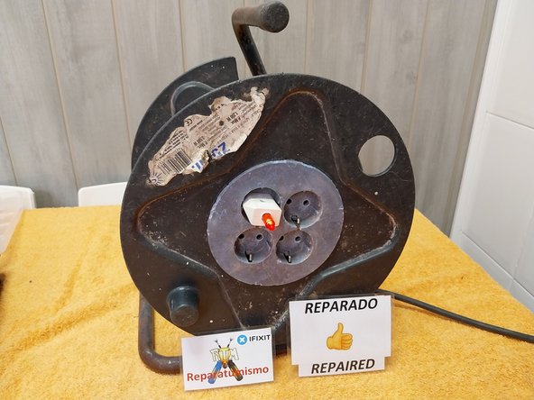
Locating and repairing a short circuit in a DIY cable reel.
ID: 163513
Description:
Steps:
- Repair of a cable winder with a SHORT CIRCUIT between the 2 Phase and Neutral wires.
- Teardown of the power socket cover; it is secured by 4 side tabs.
- Photo 1: I found both plug sockets in the outlet to be loose.
- Photo 2: Continuity measurement between the Phase and Neutral of the plug, where the multimeter should measure nothing = Insulation = 1.... the multimeter is measuring 13.4 Ohms = A SHORT CIRCUIT between wires.
- 1st Step to rule out whether the problem is in the cable or the power strip: DISCONNECT ONE OF THE CABLES FROM THE STRIP, and continue measuring at the power outlet.
- We see that when disconnecting the cable, whether it is the Brown or the Blue one, the short circuit disappears, so we can now conclude that the SHORT CIRCUIT is located in the power strip.
- Photo 1: With the 3 cables + the cable gland loose, we extract the socket base.
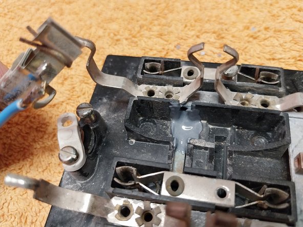
- Photo 2: Observing the base closer and with more light, we can already see at a glance the burnt, blackened area where the short circuit "spark" occurred, welding the 2 Phase and Neutral plates together, causing a permanent short circuit.
- The actual cause of the short circuit was the breakage of the plastic stems that held the 2 Phase and Neutral rails; when the jumper (wire) plate between the 2 left and right outlets passed underneath them, pulling out an inserted plug caused the short circuit.
- Photo 1: We can see that the gap between one of the poles and the plate of the other is minimal; the manufacturer simply runs the Phase plate underneath the Neutral one without any type of additional insulation.
- Photo 2: With the Neutral pole removed, we can see the Phase plate.
- Photo 3: Repair option: ROTATE the external socket and make the connection between the 2 sockets using an external wire.
- To help the plate seat better, a small notch must be made on the side of the bakelite.
- Prepare the electronics soldering iron to make the jumper (wire) between the 2 Neutral poles.
- We will check which option is best; on one hand, we must leave the cable under the connecting plate of the 2 Ground terminals. In Photo 2, we can see that by making the connection on the other side, the clearance under the Ground pole is minimal.
- Soldering the wire that connects the 2 "cut" Neutral poles.
- Once the electrical repair is complete, it is time to perform the restoration - mechanical fastening, adding insulation between the plates so that the problem does not recur.
- I use two-part fast-drying glue; it adds body and, above all, hardness to the bond.
- Dispense an equal amount of glue from both tubes and stir until the mixture has a uniform color.
- We will apply the glue under the power outlet to insulate between one outlet and the other, as well as to secure it to the base.
- Once the adhesive is applied, secure the assembly with electrical tape or duct tape so that it does not move during the drying phase.
- In my case, I let it dry for 20 hours; if you can leave it in the sun or outdoors, that is much better.
- The following day, we remove the securing tape and proceed to take measurements with a multimeter on the ohms scale, a high scale, for example 20 M ohms, to verify that the insulation between Phase - Neutral and Ground is perfect; the multimeter should not measure anything.
- Once verified, we can proceed with the reassembly of the device.
- With the device now assembled, we will check the correct connection between the power plug input and the socket outlet output for the Phase, Neutral, and Ground wires.
- We proceed to insert the outlet cover, which is simply snapped into place; since it is quite aged, it is advisable to add some reinforcements in the form of screw bosses, as there is enough space to insert them.
- Find some small, suitable sheet metal screws.
- Use a drill and a 2 mm drill bit to make the pilot holes.
- Coil the repaired cables.