Xiaomi ROBOROCK S50200 complete disassembly
ID: 164859
Description: In this guide I will show you how to completely...
Steps:
- Turn off the device by pressing and holding the power button.
- Open the cover upwards.
- Lift the dustbin upward to remove it.
- Insert the spudger from the side
- Release the clips by turning the spudger
- Lift the cover upwards
- These pictures show the front bumper already removed. This is not necessary for these instructions.
- Loosen the 6 screws for the hinges
- Lift and remove the hinges
- Remove the flap upwards
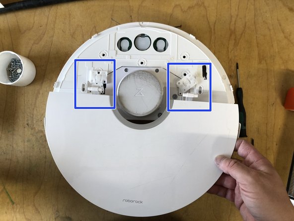
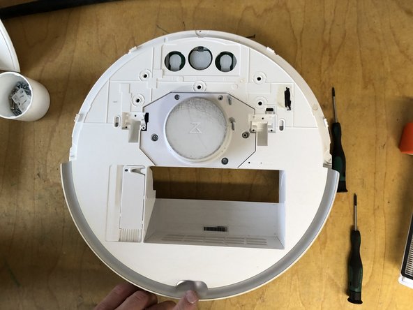
- Remove the 5 screws for the cover
- Remove the cover upwards
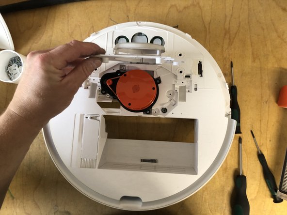
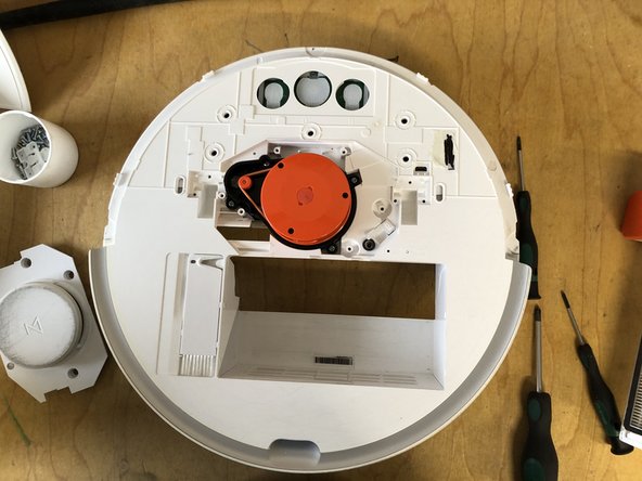
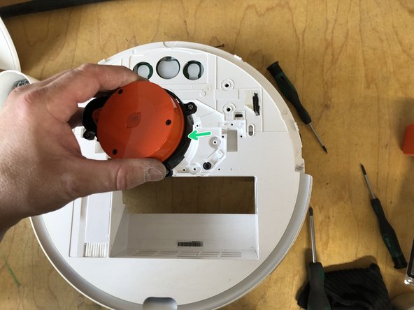
- Remove the 4 screws of the laser unit
- Remove the unit upwards (unit is still plugged into the circuit board)
- Remove the main brush holder by pressing both locks inward and lifting it up.
- Remove the main brush.
- Remove the screw holding the side brush.
- You don't need to completely unscrew the screw; simply loosen it and remove it with the brush.
- Remove the side brush along with the screw by lifting it upward.
- Lift the front wheel with the screwdriver.
- Completely pull the front wheel upward to remove it.
- Remove the seven screws holding the bottom panel.
- Lift the bottom cover up.
- Lift the battery using the two tabs.
- Disconnect the connector.
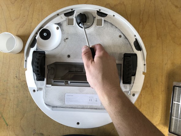
- Remove the four screws from the main brush assembly
- Lift out the main brush assembly upwards
- Remove the 8 screws from the underside of the bumper
- Remove the strip
- Pull the bumper forwards, taking care not to bend the two metal plates
- In the pictures another lip is mounted, which is not present in the original condition
- The pictures show that the floor has already been removed, this is not necessary for this repair
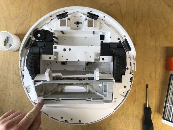
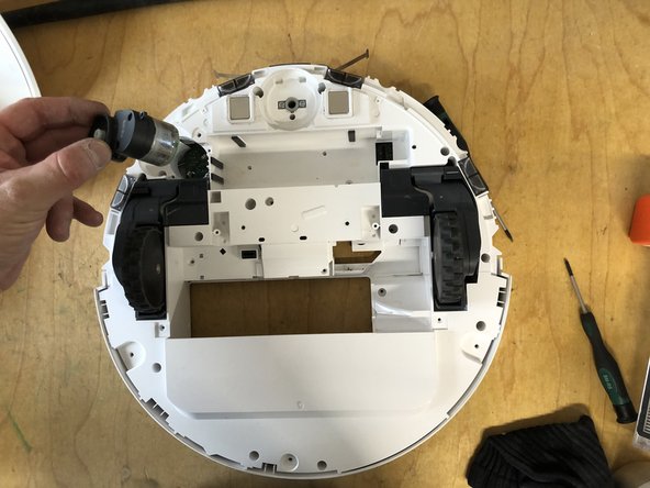
- Remove the three screws from the motor
- Pull the motor out upwards (plug connection with the circuit board)
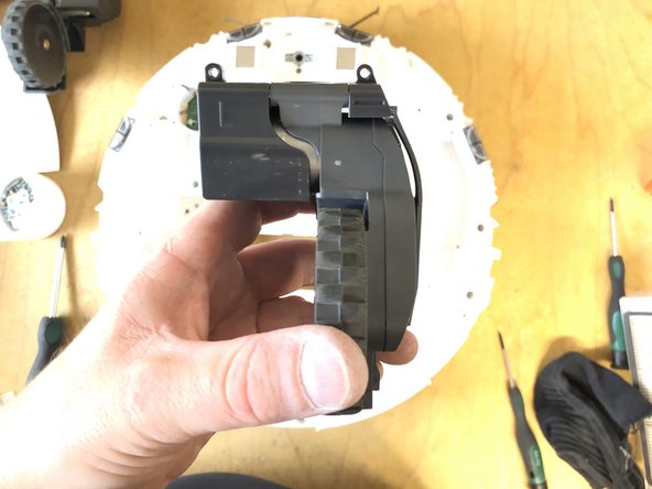
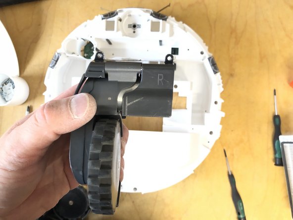
- remove the three screws from the drive unit
- Remove wheel upwards (connected to a circuit board via plug connection)
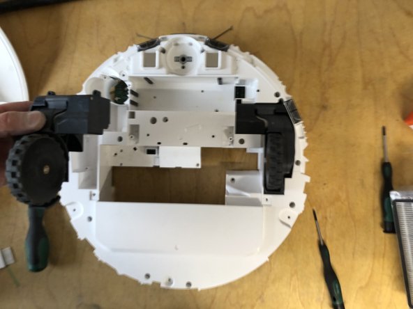
- Remove the three screws from the drive unit
- Remove the wheel upwards (connected to the circuit board via a plug connection)
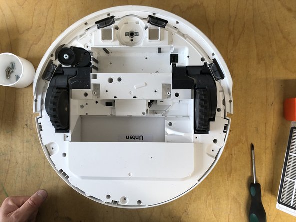
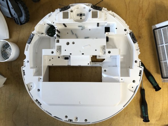
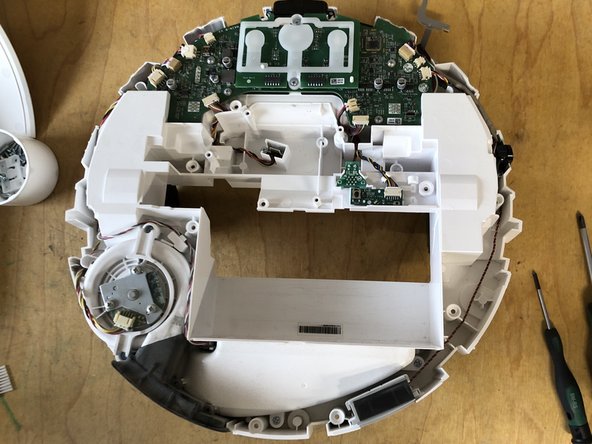
- Remove the 17 screws on the underside
- Lift the cover upwards