Repair Hoover airflow steam iron TIF2600
ID: 165110
Description: Hoover airflow steam iron TIF2600 needed a...
Steps:
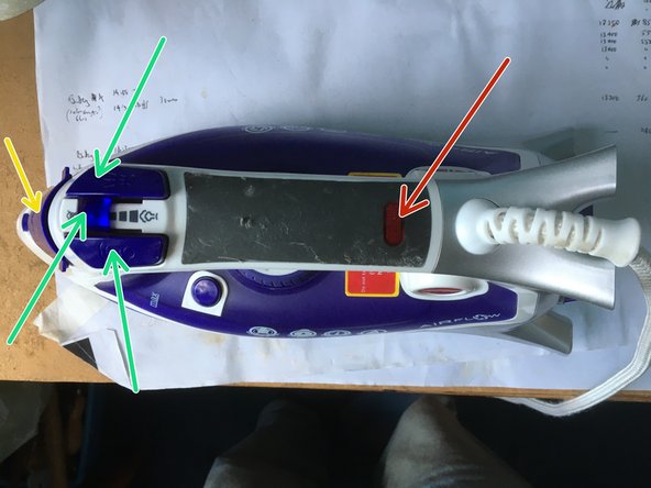
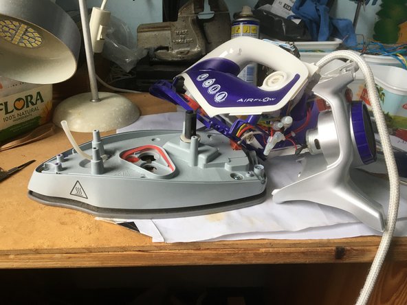
- Shows side and top view of iron before disassembly. The red arrow shows the lamp cover which must be prised off and the hidden screw exposed, must be removed. Also remove screw under the water lid (yellow arrow). Prise off the two pump buttons and adjacent slider (green arrows)
- Tips: Take photos as you go along. Make a note of which screws go where. Screws can be defined by length, thread (fine or coarse), pointed or blunt, head size, with or without washers etc. Put screws and parts in boxes labelled eg 1-10 in the order they were extracted.
- The upper half of the handle can now be partially prised off. Start at rear end. (note it is held on by plastic clips)
- To fully remove upper half of handle, pull off collar and hose (green arrow) from spray nozzle. Pull out lamp.
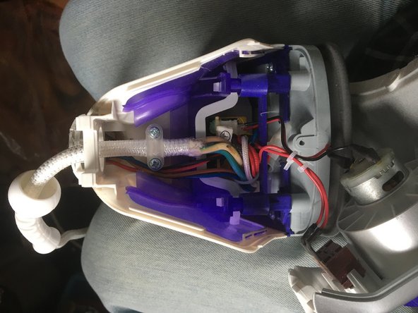
- To gain access to the power cord and other wiring as shown in the image, remove the back cover as follows. Prise out the two rubber feet and remove hidden screws. Remove screw by the part number label under the fan. Prise off cord cover remove two exposed screws and prise off rear cover.
- It's a good idea to check continuities in the power cord with the multimeter. (Push a pin or similar into the opening of the insulated crimps to get electrical contact.)
- To remove the main cover, prise off the temperature dial (and safely store the spring and ratchet) and remove the two now exposed screws.
- Remove numerous other screws that are now visible, including the one down the hole by the cord inlet. Remove pumps taking care not to loose ball bearings and springs. Safely store the temperature dial post and washers (rubber washer above metalwasher).
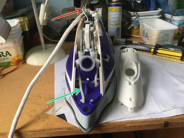
- Remove the purple frame with vent sandwiched between the main cover and grey casing, by undo the obvious screws. the iron should now look like this image
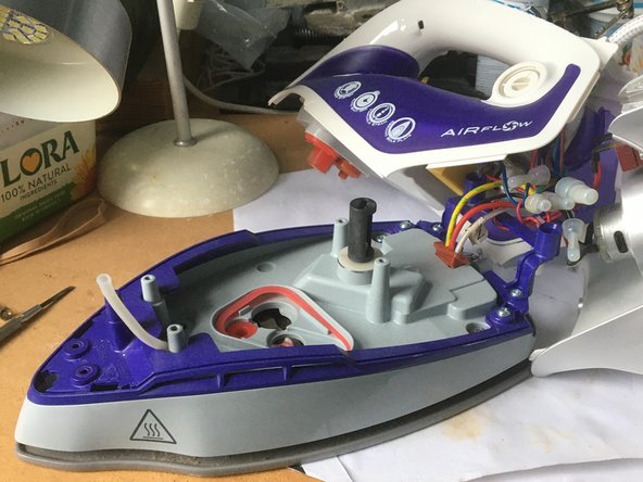
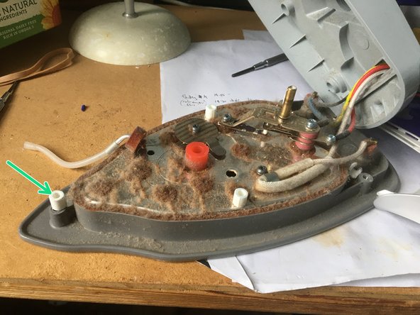
- Undo the final three screws to lift off the grey cover. Guide the rubber hose and pipework out through the hole. Note there are five white ceramic spacers (eg green arrow) so the hot sole plate does not melt the grey casing. Screws go though 3 of the spacers. These spacers locate into cups in the grey casing.
- Note the metal sole plate is very dusty as is normal. Clean, being carefully not to get dirt down exposed holes.
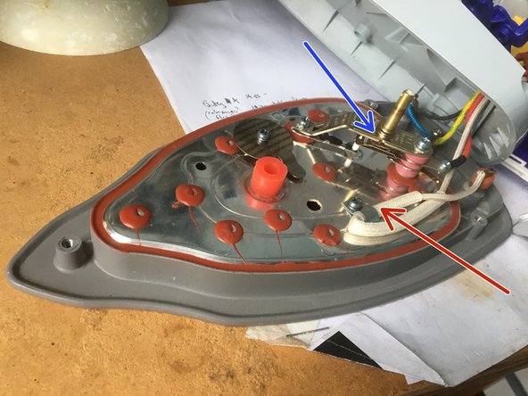
- Continuity checks showed there was infinite resistance across the thermostat contacts (blue arrow). These were cleaned with the finest abrasive card (1800 grit?) to give a satisfactory 0 ohms with contacts closed.
- Some irons fail due to a blown thermal fuse (red arrow) if temperature goes above 240C in this case. To test, loosen fixture and slide away insulation sleeve to expose the thermal fuse. Check it is a satisfactory 0 ohms across the ends. Also check the heating element for continuity (22ohms in my case).
- Note: if replacing a thermal fuse, check the amps as well as the temperature are matched. If the current is too high there can be additional heating within the thermal fuse which gets worse with time, reducing its life. PS I have seen a 10A (240C) thermal fuse in a 11A iron which needed changing after a few years. What some manufacturers will do!
- Test on reassembly. Note this iron has a tilt switch. When in the upright position, the lamp will blink and beep. The iron wont heat up until turned into the horizontal when it uses 2800W. Also a good idea to give the iron a 'self clean' (see instruction manual) in case dirt got into the steam chamber)