Razer Naga Epic Mouse Initial Disassembly
ID: 165161
Description: How to perform the initial disassembly of the R...
Steps:
- Turn your device upside down to see the back.
- Turn the left switch to the downward position turn off wireless mode and stop the device from drawing power from the battery.
- This switch label for the off position seems to be different for some units. Depending on your device, this might either be labelled as 'OFF' or 'CHARGING'.
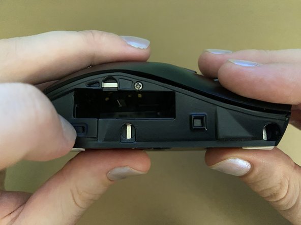
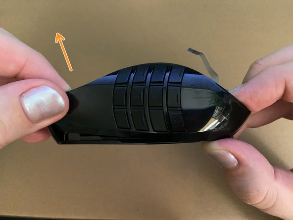
- Gently pull the magnetic side grip away from the mouse and set it aside.
- The battery compartment is now visible on the exposed side where the grip was attached.
- Using your fingernail or a spudger, pull the battery release switch to the left to release the battery.
- The battery is spring loaded, so it should pop out, letting you grip it and pull it out of the device.
- If the battery won't come out, it could be swollen. Leave it there - you will have an opportunity to push it out from the inside later.
- Unfortunately my mouse does not have a battery in it (it got swollen a long while ago and I didn't replace it), so you'll have to imagine there's a rectangle-shaped battery in there 😅
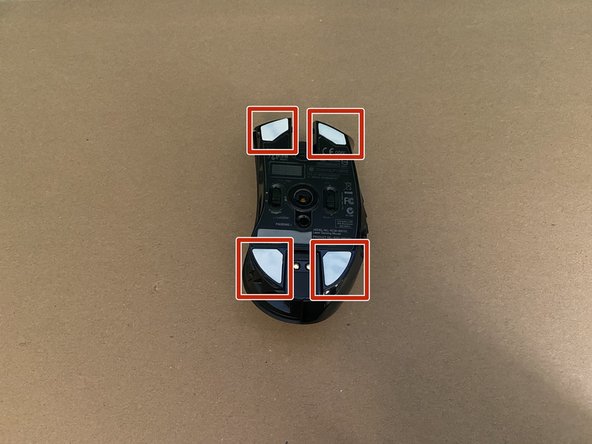
- Turn your mouse over, bottom up.
- There are 4 mouse feet concealing screws on each corner of the mouse.
- The mouse comes with black feet, but I've replaced my mouse feet once before, and these replacements are white.
- You will not be able to re-use the mouse feet once you've taken them off. Make sure you have replacements available.
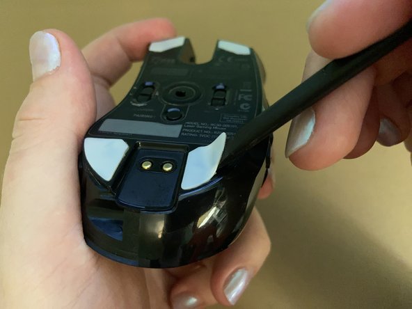
- For each of the 4 mouse feet mentioned in the previous step, peel those mouse feet off with a spudger to reveal the screws underneath.
- When re-assembling, clean the glue residue off the surfaces and dry them before applying new feet.
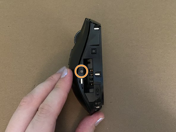
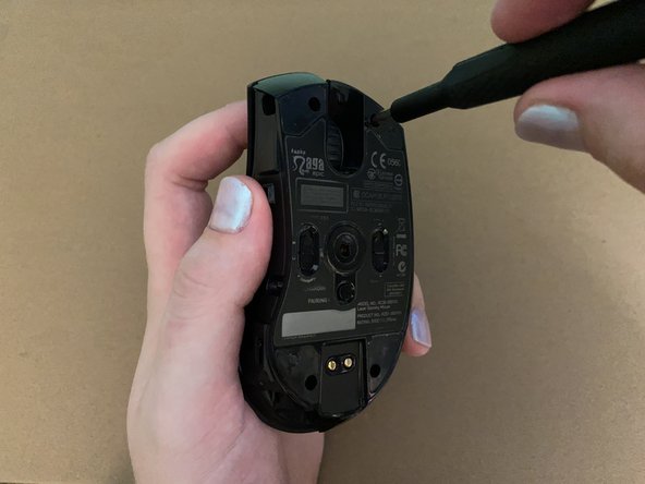
- There are 5 outer case screws you need to remove:
- 4 x 9mm Phillips #0 screws on the bottom
- 1 x 6mm Phillips #0 screw on the side above the battery compartment
- If you couldn't remove your battery in the earlier step, be careful and make sure you don't puncture the battery with the screwdriver.
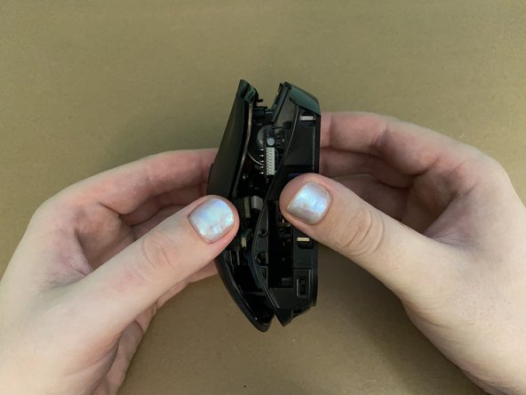
- Gently separate the top asssembly from the rest of the device, pulling slightly leftwards like a book.
- Do not try to fully remove the top assembly yet, as it's attached to the bottom and side with ribbon cables.
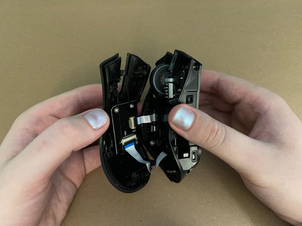
- Lay the device down with the top panel lying upside down on the table and the rest of the device laying on its side.
- The top panel is connected to the rest of the device by two ribbon cables:
- Ribbon cable connecting the top panel to the mainboard.
- Ribbon cable connecting the number pad to the top panel.
- Using a spudger, carefully flip up the latches on the ZIF connectors on the top panel and gently pull those ribbon cables away.
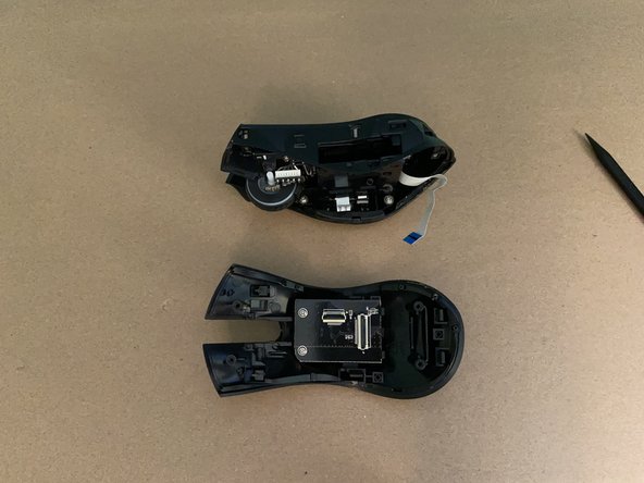
- Now the top panel is free from the rest of the device!
- If you just need to disassemble the top panel, you can stop here and move to the Top Panel Disassembly Guide.
- Separating the other two sections of the mouse can be tricky, so its best not to if you don't have to!
- Dealing with the numpad is both tricky and requires force. I am separating the disassembly and reassembly steps as they require different techniques. This step is for disassembly only.
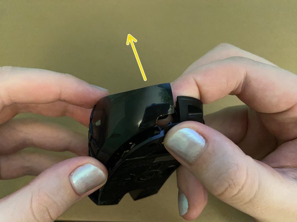
- Hold the numpad casing and bottom casing together at the rear end.
- While holding the back end together, gently pull the front of the numpad casing away until it won't gently pull away any further.
- Now carefully pull the the numpad casing off of the bottom casing from the rear.
- The two should come apart effortlessly at this point, but as I mention in one of the re-assembly steps, I broke the casing a little at the back when attempting this before so it may require more care and a slightly different approach.
- This step is for reassembly only.
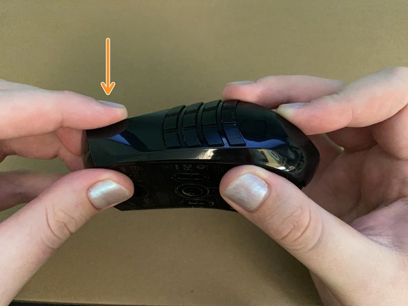
- While holding the back divot/hole in place, lay the front of the numpad panel relatively straight over the bottom panel.
- Holding the rear sections of the two panels together are important as the plastic is thin on the bottom assembly here and it can easily bend if you try to apply downward force here.
- Firmly press the numpad panel into the bottom panel at the front. The two should snap together.
- This step is for reassembly only.
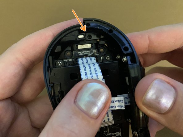
- On the rear of the bottom panel towards the center there should be a circular plastic divot. This aligns the bottom and numpad panels at the rear.
- You can see here how I've already bent the plastic on mine. This is why you need to be careful!
- Insert the corresponding hole on the numpad panel over the divot on the bottom panel. Make sure they are properly seated.
- The numpad can now be fully separated from the bottom housing and mainboard of the device.