Mac Studio 2023 Antenna 1 Replacement
ID: 165230
Description: Use this guide to replace the left antenna...
Steps:
- Completely shut down your Mac Studio.
- Unplug all cables from your device.
- Flip your Mac Studio over and lay it down so the bottom faces up and the SD card slot and two front USB‑C ports are facing you.
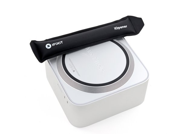
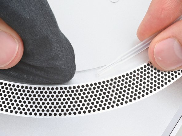
- Adhesive strips secure the bottom cover screw pad.
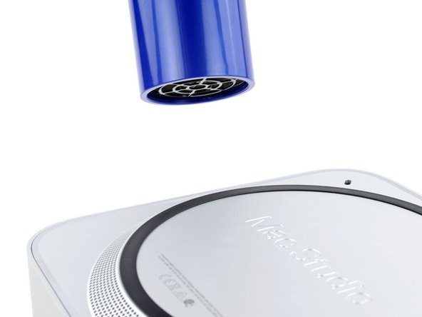
- Heat an iOpener and lay it over one of the bottom cover screws for two minutes to soften the adhesive near the screw—this is where you'll insert a spudger in the next step.
- You can also use a hair dryer or heat gun, but be careful as extreme heat will warp the pad.
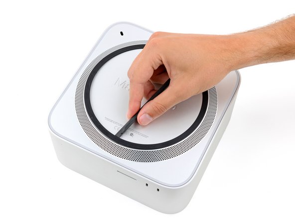
- Insert the point of a spudger under the pad's inner edge, near the screw you applied heat to in the previous step.
- This may take some force. If you're having trouble, apply more heat and try again.
- Use the spudger to lift the pad and separate the adhesive.
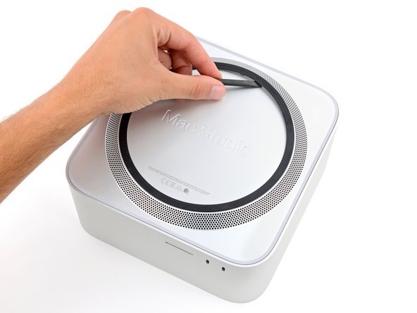
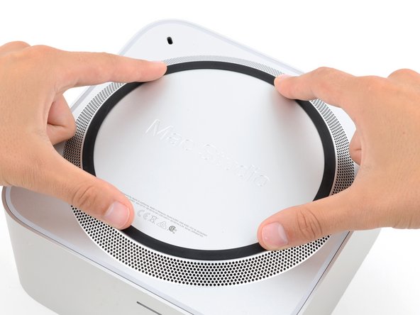
- Insert the flat end of a spudger under the pad.
- Slide the spudger under the entire pad to separate the remaining adhesive.
- Remove the bottom cover screw pad.
- During reassembly:
- If the adhesive strips are still sticky, you can reuse them.
- If you're applying new adhesive:
- Use the flat end of a spudger and your fingers to scrape up and remove the old adhesive strips.
- Use isopropyl alcohol and a microfiber cloth to remove the old adhesive residue.
- If you don't have replacement adhesive, you can use strips of thin, double-sided tape 2–3 mm wide.
- Apply the new adhesive strips to the bottom cover and remove their liners.
- Firmly press the bottom cover screw pad into its recess to secure it.
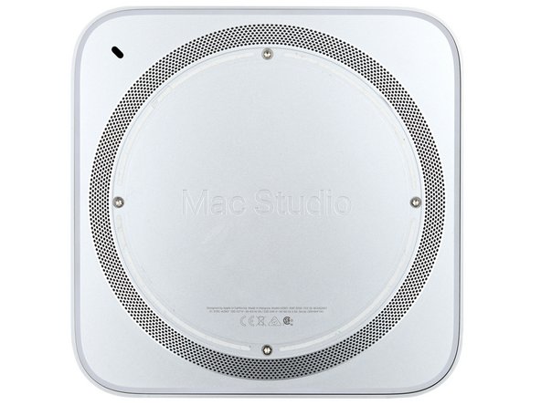
- While the Mac Studio uses Torx Plus screws, standard Torx bits work. Make sure to apply constant, downward force to prevent stripping.
- Use a T10 Torx screwdriver to remove the four 8 mm‑long screws securing the bottom cover.
- Throughout this repair, keep track of each screw and make sure it goes back exactly where it came.
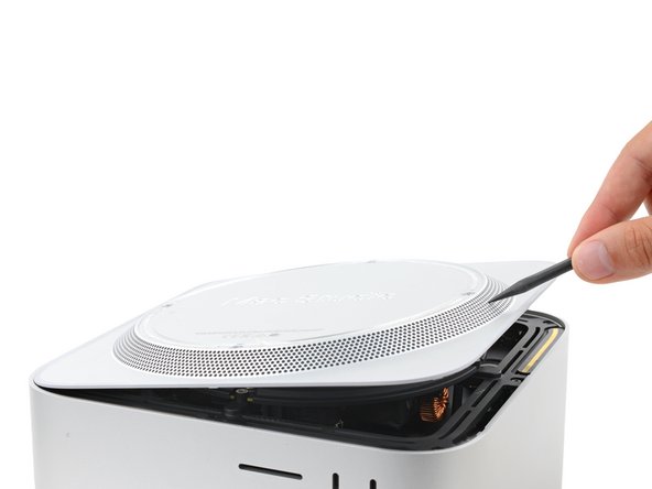
- Insert the point of a spudger in one of the bottom cover's ventilation holes and lift the cover until you can grab it with your fingers.
- Remove the bottom cover.
- To orient the bottom cover, align the Kensington lock cutout in the top left corner with the corresponding one on the internal frame.
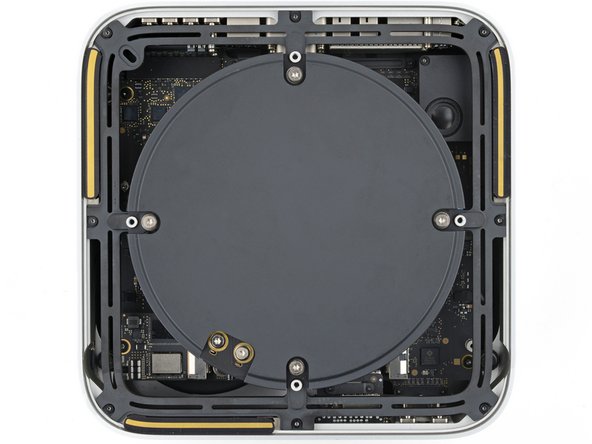
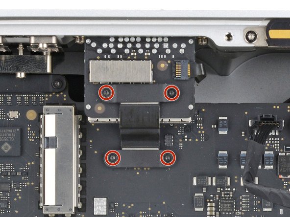
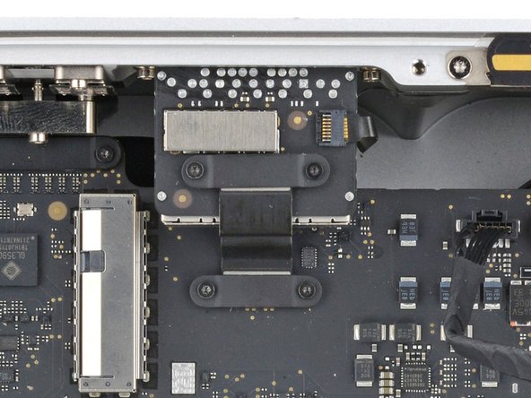
- Use a T10 Torx screwdriver to remove the six screws securing the power supply:
- Four 6 mm‑long screws
- Two 7 mm‑long screws with washers
- You may need to remove a sticker to access these screws. If you do, save it for reassembly.
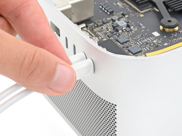
- Flip your Mac Studio around so the rear ports are facing you.
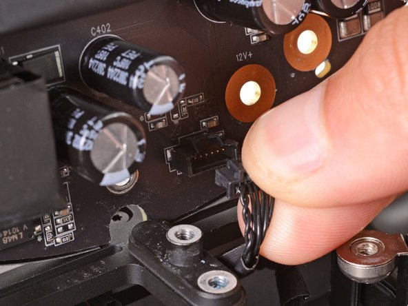
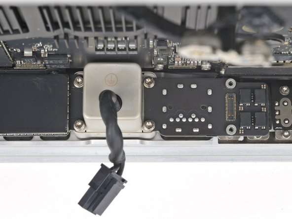
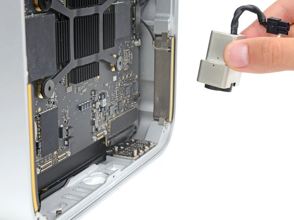
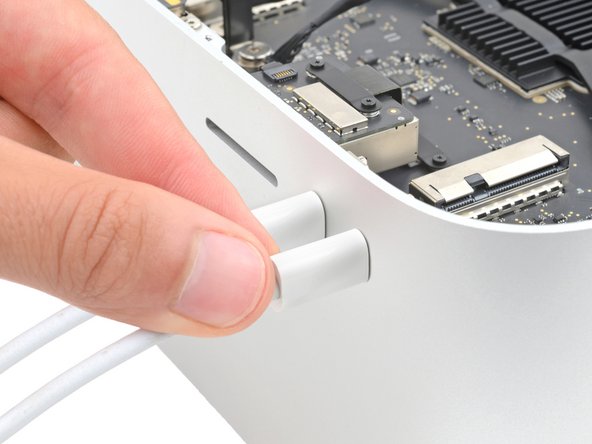
- A tight plastic latch secures the power cord port cable.
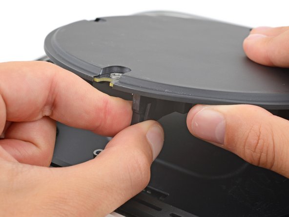
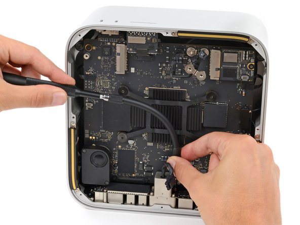
- Firmly hold the power supply with one hand and lift up the edge near the power cord port.
- With your free hand, pinch the head of the power cord port connector to unclip it and pull straight down to disconnect the cable.
- Only grab the power supply by its edges. Various power components and capacitors are left exposed.
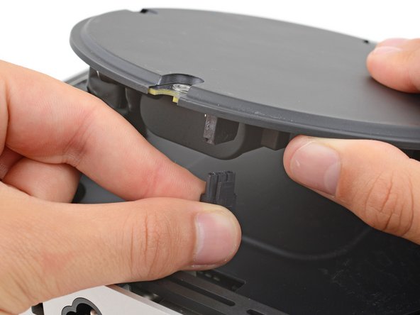
- Carefully tilt the power supply away from the power cord port so it's at a 90-degree angle.
- Be careful not to strain the cable that's still connected to the power supply.
- Keep the power supply tilted up for the next step.
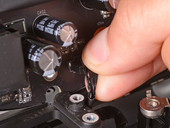
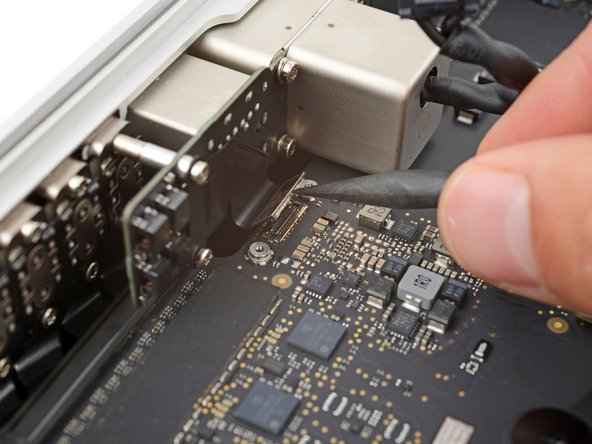
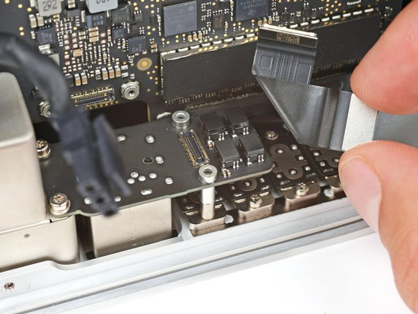
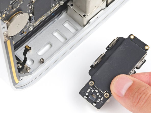
- A delicate plastic clip secures the power supply signal cable.
- With your free hand, pinch the head of the power supply connector to unclip it and pull straight away from the socket to disconnect the cable.
- Remove the power supply.
- Flip your Mac Studio around so the SD card reader and two front USB‑C ports are facing you.
- Use a T6 Torx screwdriver to remove the eight screws securing the internal frame:
- Seven 5 mm‑long screws
- One 4 mm‑long screw
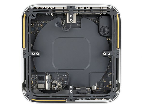
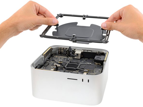
- Slowly lift the internal frame straight up and remove it, making sure no cables get snagged.
- During reassembly, make sure the power supply signal cable and power cord port cable don't get stuck under the frame when lowering it into place.
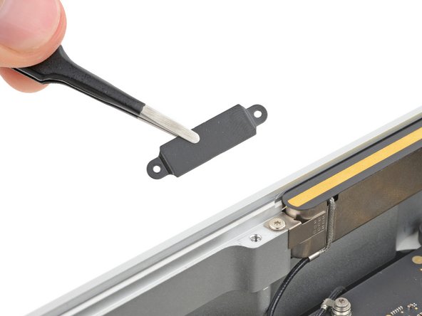
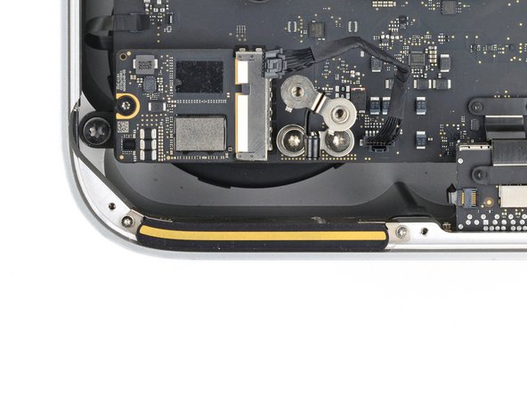
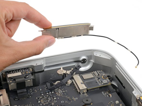
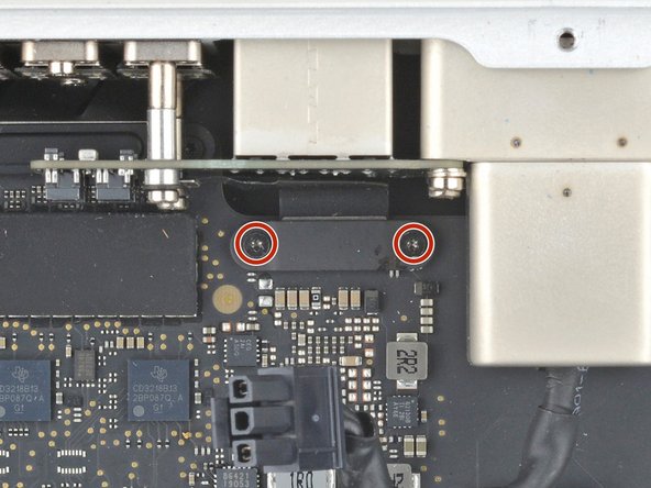
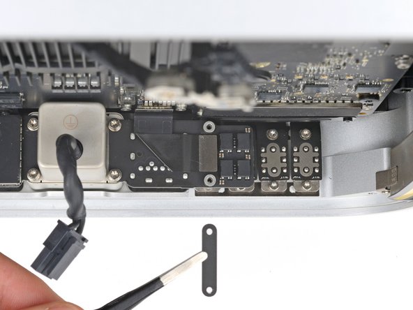
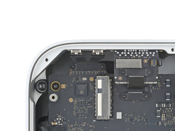
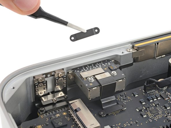
- Use a T3 Torx screwdriver to remove the two 2 mm‑long screws securing the antenna cable cover.
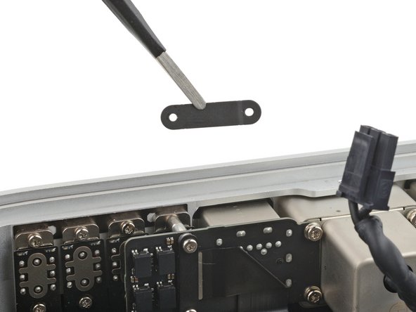
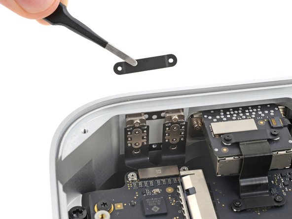
- Use tweezers or your fingers to remove the cover.
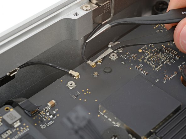
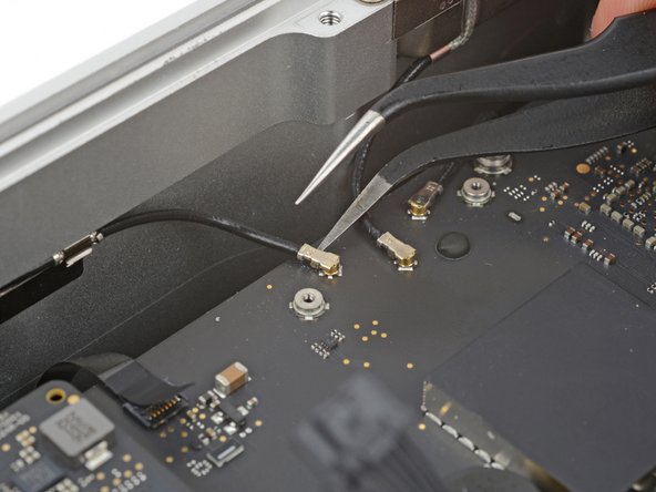
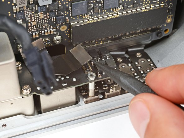
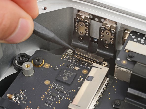
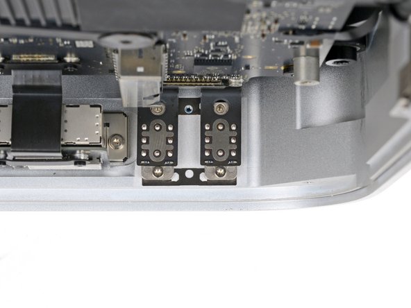
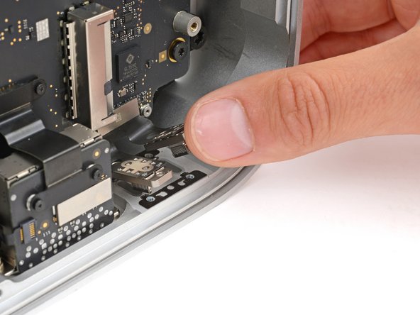
- Insert one arm of a pair of angled tweezers under the metal neck of antenna 2's coaxial connector and lift straight up to disconnect it.
- To reconnect the cable, hold the connector in place over its socket and press down with the flat end of a spudger—the connector should snap into place. If you're having trouble, don't try to force the connector over the socket. Reposition it and try again.
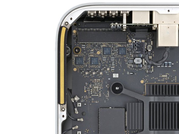
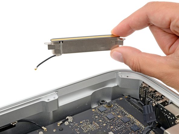
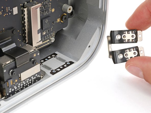
- Use a T5 Torx screwdriver to remove the two 3.5 mm‑long screws securing antenna 2.
- Remove antenna 2.
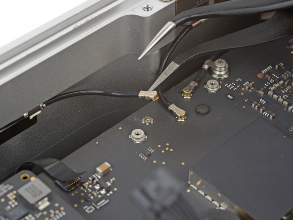
- Insert one arm of a pair of angled tweezers under the metal neck of antenna 3's coaxial connector (next to antenna 2's connector) and lift straight up to disconnect it.
- To reconnect the cable, hold the connector in place over its socket and press down with the flat end of a spudger—the connector should snap into place. If you're having trouble, don't try to force the connector over the socket. Reposition it and try again.
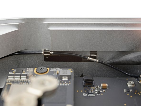
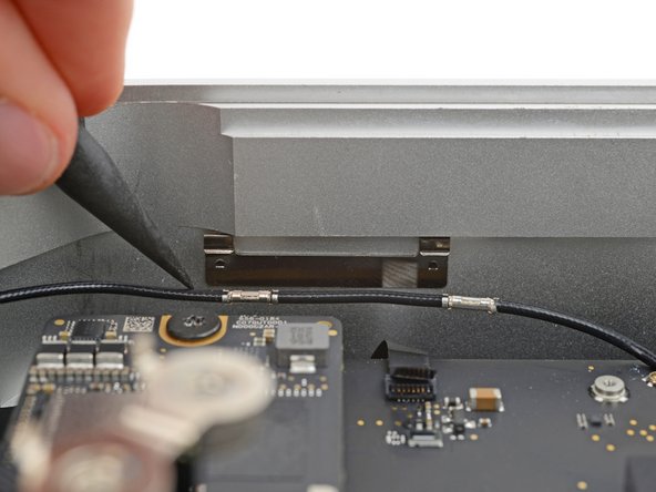
- Use the point of a spudger to push antenna 3's cable down and unclip it.
- During reassembly, use the flat end of a spudger to push the cable's metal sleeves into their clips.
- Use a T5 Torx screwdriver to remove the two 3.5 mm‑long screws securing antenna 3.
- Remove antenna 3.
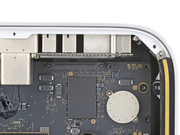
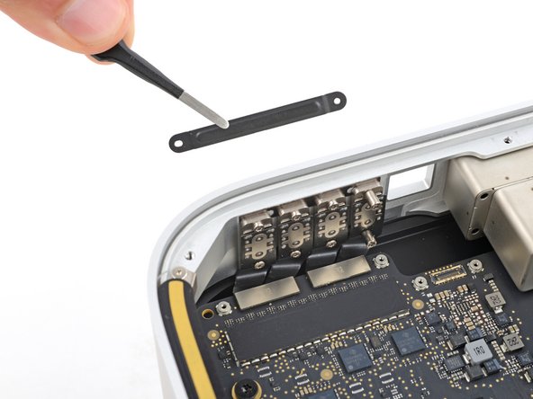
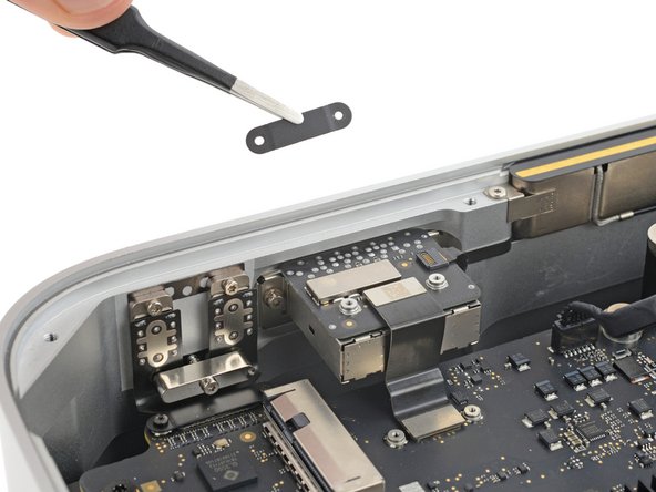
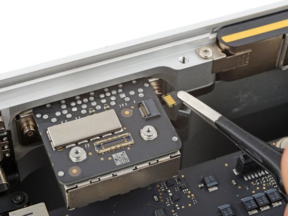
- Use a T3 Torx screwdriver to remove the two 2 mm‑long screws securing the ethernet board cable cover.
- Use tweezers or your fingers to remove the cover.
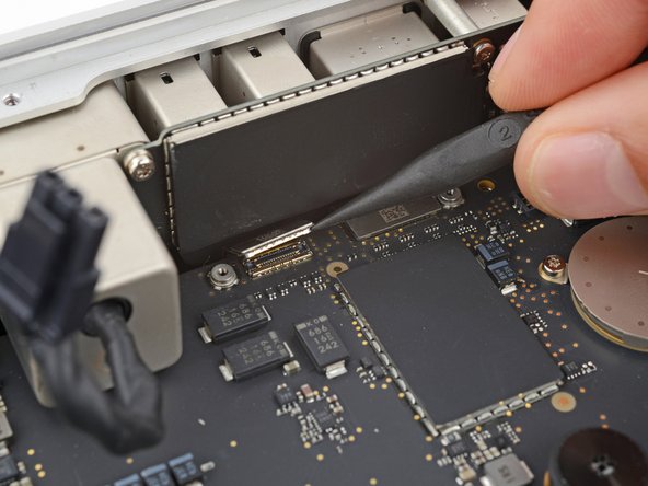
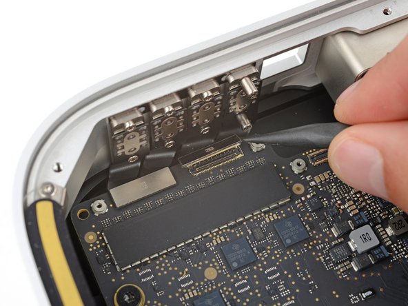
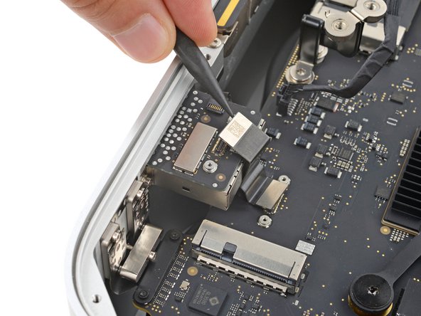
- Be very careful not to scrape off or damage any surface mounted components during this step.
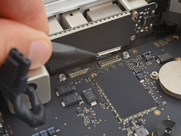
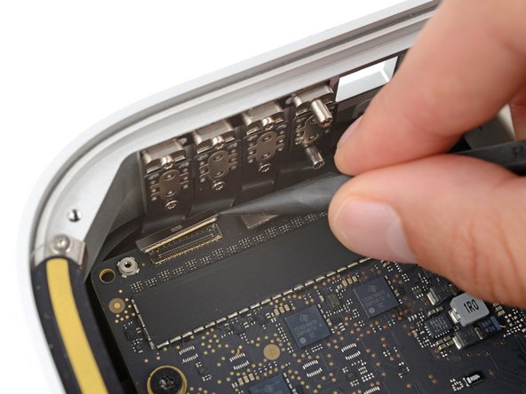
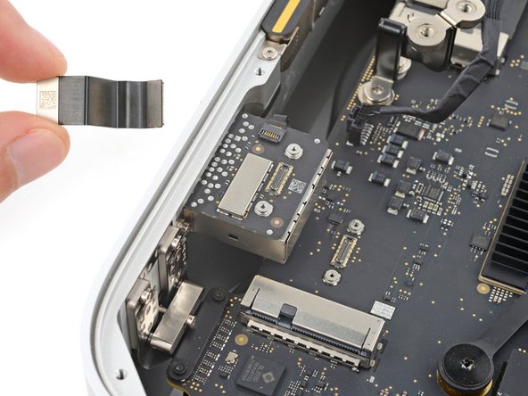
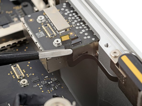
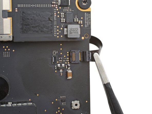
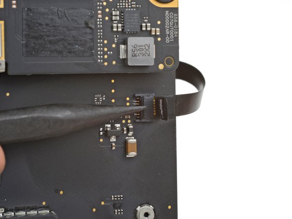
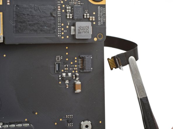
- Use a spudger to pry up and disconnect the ethernet board cable press connector from the logic board.
- To reconnect press connectors, carefully align and press down on one side until it clicks into place, then repeat on the other side. Don't press down in the middle. If the connector is misaligned, the pins can bend and cause permanent damage.
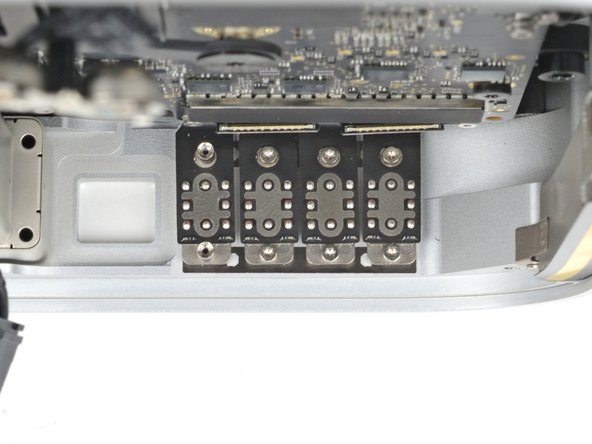
- Carefully stand up your Mac Studio so the SD card reader and two front USB-C ports are facing up.
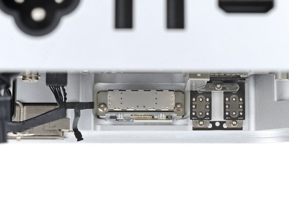
- Use a T4 Torx screwdriver to remove the two 11 mm‑long screws securing the right side of the ethernet board and its cover.
- These screws may be hard to access. If you can't insert your screwdriver properly, use a flexible extension to avoid stripping screws or damaging the logic board.
- Use tweezers or your fingers to remove the cover.
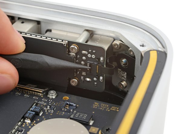
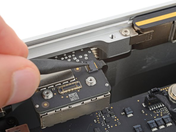
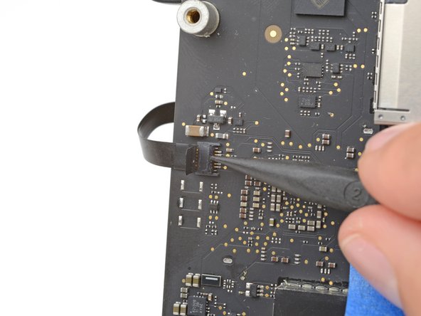
- Insert the point of a spudger under the bottom right corner of the ethernet board press connector and lift up to disconnect it.
- Don't pry against any surface mounted components.
- Remove the cable.
- These screws may be hard to access. If you can't insert your screwdriver properly, use a flexible extension to avoid stripping screws or damaging the logic board.
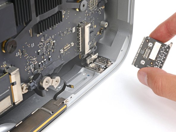
- Use a T6 Torx screwdriver to remove the two 20 mm‑long screws (with washers) securing the ethernet board.
- Be careful not to lose the washers, as they can fall off easily.
- Lift the ethernet board out of its recess and remove it.
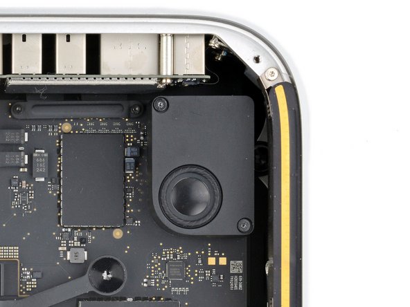
- Reposition your Mac Studio so the SD card reader and two front USB‑C ports are facing you.
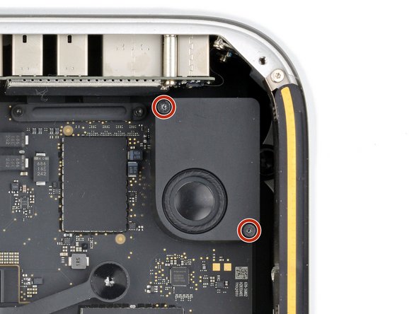
- Use a T5 Torx screwdriver to remove the two 12 mm‑long screws securing the speaker.
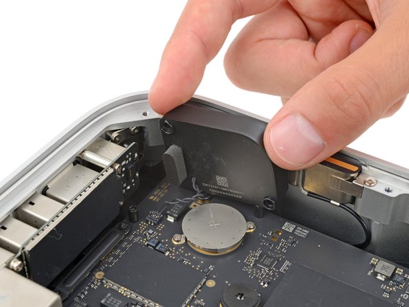
- Lift the inner edge of the speaker and stand it upright so you can access its connector on the logic board.
- During reassembly, line up the screw holes on the bottom of the speaker with their posts on the logic board.
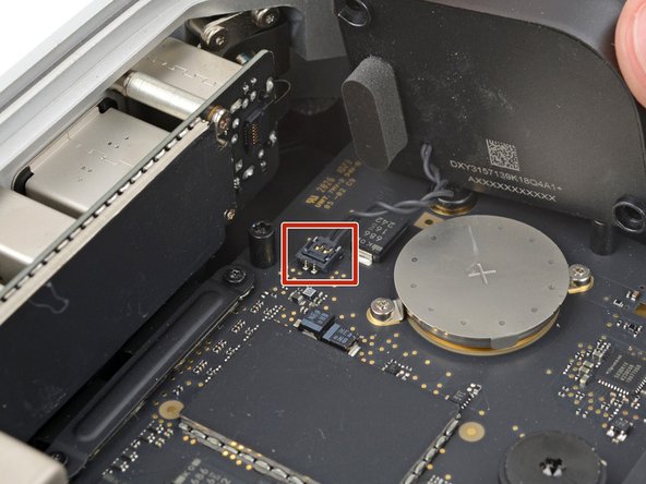
- Insert the point of a spudger under the speaker connector's plastic head and carefully lift it straight up and out of its socket.
- Don't lift on the wires themselves, or you may damage them.
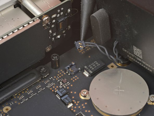
- To reconnect the cable, position the connector head over its socket and press to with the flat end of a spudger—the connector should click into place.
- Remove the speaker.
- Use a T3 Torx screwdriver to remove the two 2 mm‑long screws securing the I/O board cable cover.
- Use a T8 Torx screwdriver to remove the standoff screw just to the right of the cover.
- Use tweezers or your fingers to remove the I/O board cable cover.
- Be very careful not to scrape off or damage any surface mounted components during this step.
- Use a spudger to pry up and disconnect both of the I/O board's press connectors.
- To reconnect press connectors, carefully align and press down on one side until it clicks into place, then repeat on the other side. Don't press down in the middle. If the connector is misaligned, the pins can bend and cause permanent damage.
- Use the point of a spudger or a clean fingernail to flip up the hinged locking flap on the power button cable ZIF connector, located on the outer edge of the I/O board.
- Use tweezers to gently pull the cable straight out of its socket.
- Carefully stand up your Mac Studio so the SD card reader and two front USB-C ports are facing up.
- These screws may be hard to access. If you can't insert your screwdriver properly, use a flexible extension to avoid stripping screws or damaging the logic board.
- Use a T4 Torx screwdriver to remove the two 15.5 mm‑long screws securing the outer edge of the I/O board.
- Use a T6 Torx screwdriver to remove the two 20 mm‑long screws securing the inner edge of the I/O board.
- During reassembly:
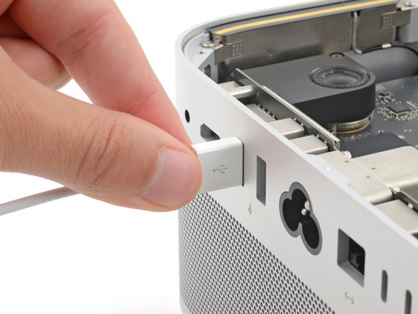
- Partially tighten the four screws securing the board.
- Lay your Mac Studio down and plug a cable into one of the ports to ensure proper fit and alignment, adjusting the port as necessary—the cable should be easy to insert and remove.
- With the cable plugged in and the board in position, fully tighten all four screws.
- Unplug all cables before continuing.
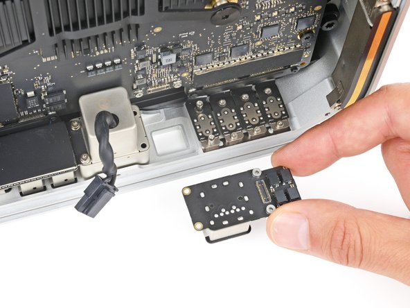
- Lift the I/O board straight up and out of its recess to remove it.
- During reassembly, lower the board into its recess, making sure the press connectors don't get trapped under the logic board.
- Lift the power cord port out of its recess and remove it.
- Flip your Mac Studio around so the rear ports are facing you.
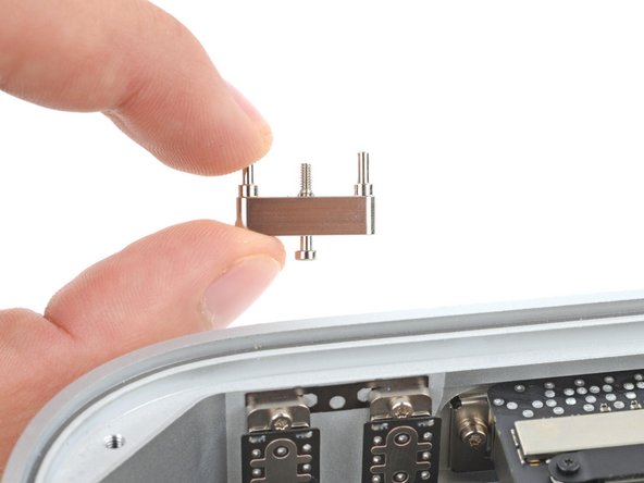
- Use a T5 Torx screwdriver to fully loosen the 12.3 mm‑long screw securing the USB-C bracket.
- The screw may be hard to access. If you can't insert your screwdriver properly, use a flexible extension to avoid stripping the screw or damaging the logic board.
- Remove the USB-C bracket.
- Use a T3 Torx screwdriver to remove the two 2 mm‑long screws securing the USB‑C port cable cover.
- Use tweezers or your fingers to remove the cover.
- Be very careful not to scrape off or damage any surface mounted components during this step.
- Use the point of a spudger to pry up and disconnect the USB‑C port press connector from the logic board.
- To reconnect press connectors like this one, carefully align and press down on one side until it clicks into place, then repeat on the other side. Don't press down in the middle. If the connector is misaligned, the pins can bend and cause permanent damage.
- Carefully stand up your Mac Studio so the rear ports face up.
- Use a T5 Torx screwdriver to remove the two 5 mm‑long screws securing the USB-C ports.
- These screws may be hard to access. If you can't insert your screwdriver properly, use a flexible extension to avoid stripping screws or damaging the logic board.
- During reassembly:
- Partially tighten the two screws securing the top of the ports.
- Put the USB-C bracket into place and partially tighten the screw that secures it.
- Lay your Mac Studio down and plug a cable into each port to ensure proper fit and alignment, adjusting the ports as necessary—the cables should be easy to insert and remove.
- With both cables plugged in and the ports in position, fully tighten all three screws.
- Unplug any cables before continuing reassembly.
- Use your fingers to lift the ports out of their recesses and remove them.
- Don't try to remove an individual port. A flex cable connects them and can easily be damaged.
- During reassembly, put the ports into their recesses, making sure the press connector stays above the logic board.
- Reposition your Mac Studio so the SD card reader and two front USB‑C ports are facing you.
- Use a T3 Torx screwdriver to remove the two 2 mm‑long screws securing the back Thunderbolt 4 port cable cover.
- Use tweezers or your fingers to remove the cover.
- Be very careful not to scrape off or damage any surface mounted components during this step.
- Use a spudger to pry up and disconnect both Thunderbolt 4 cable press connectors from the logic board.
- To reconnect press connectors, carefully align and press down on one side until it clicks into place, then repeat on the other side. Don't press down in the middle. If the connector is misaligned, the pins can bend and cause permanent damage.
- Carefully stand up your Mac Studio so the SD card reader and front two USB-C ports face up.
- These screws may be hard to access. If you can't insert your screwdriver properly, use a flexible extension to avoid stripping screws or damaging the logic board.
- Use a T5 Torx screwdriver to remove the six 5 mm‑long screws securing three of the ports.
- Use a T7 Torx screwdriver to remove the two 8 mm‑long standoff screws securing the remaining port.
- To align and install a set of ports during reassembly:
- Partially tighten all four screws on a set of ports.
- Lay your Mac Studio down and plug a cable into each port to ensure proper fit and alignment, adjusting the ports as necessary—the cable should be easy to insert and remove.
- With both cables plugged in and the port in position, fully tighten the screws.
- Unplug all cables before continuing with reassembly.
- Flex cables connect the two inner and two outer port pairs. Don't try to remove individual ports—you can easily damage the cables that connect them.
- Use your fingers to lift the two inner or outer ports out of their recesses and remove them.
- Repeat the process to remove the two other ports.
- During reassembly, put the ports into their recesses, making sure the press connectors stay above the logic board.
- Reposition your Mac Studio so the power cord port is facing you.
- Use a T3 Torx screwdriver to remove the four 2 mm‑long screws securing the SDXC card reader cable covers.
- Use tweezers or your fingers to remove the two cable covers.
- Be very careful not to scrape off or damage any surface mounted components during this step.
- Use the flat end of a spudger to pry up and disconnect the card reader cable press connector from the logic board.
- Use the point of a spudger to disconnect the cable's other press connector from the reader itself.
- Remove the cable.
- To reconnect press connectors, carefully align and press down on one side until it clicks into place, then repeat on the other side. Don't press down in the middle. If the connector is misaligned, the pins can bend and cause permanent damage.
- Use the point of a spudger or a clean fingernail to flip up the hinged locking flap on the status indicator light cable ZIF connector, located on the right side of the card reader.
- Use tweezers to gently pull the cable straight out of its socket.
- Very light adhesive secures the cable to the side of the card reader.
- Use tweezers to gently pull the cable away from the card reader and separate the adhesive.
- Carefully stand up your Mac Studio so the rear ports face up.
- Use a T5 Torx screwdriver to remove the two 6 mm‑long screws securing the card reader.
- These screws may be hard to access. If you can't insert your screwdriver properly, use a flexible extension to avoid stripping screws or damaging the logic board.
- Remove the card reader.
- Reposition your Mac Studio so the power cord port is facing you.
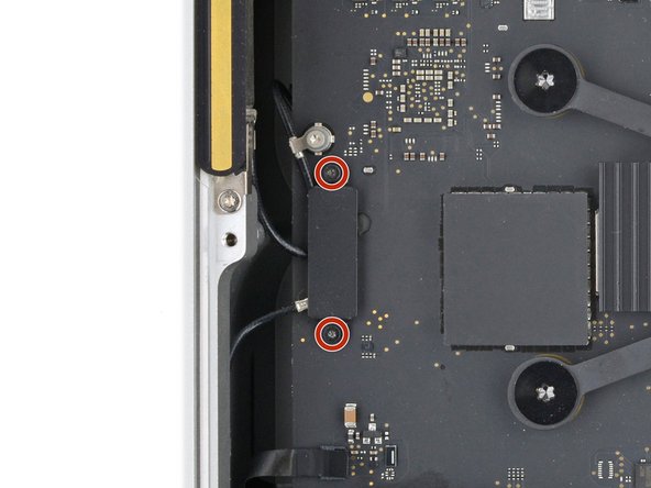
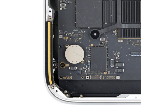
- Use a T5 Torx screwdriver to remove the two 3.5 mm‑long screws securing antenna 1.
- Be very careful not to scrape off or damage any surface mounted components during this step.
- Gently lay antenna 1 to the left of the heatsink, being careful not to strain its cable.
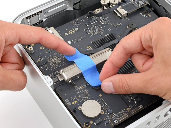
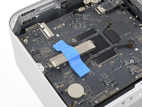
- Secure antenna 1 to the logic board with a strip of painters tape.
- Stick the tape to the heatsink screws, not directly onto the board.
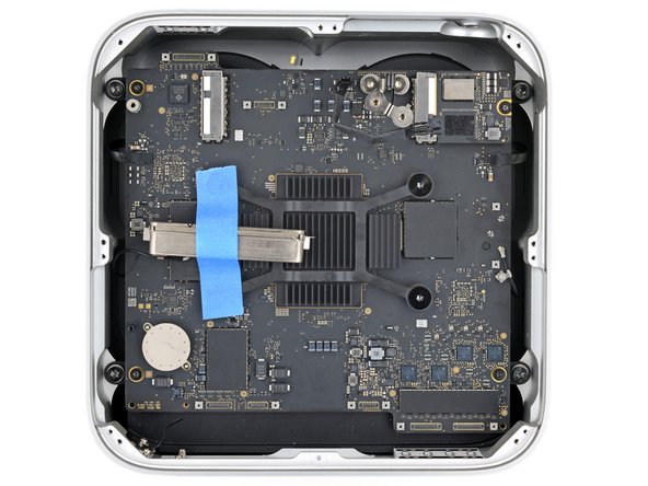
- Use a T20 Torx screwdriver to remove the four 12 mm‑long screws securing the logic board assembly.
- Before trying to remove the logic board assembly, note the following:
- The assembly sits very snugly in its housing. Take your time and don't try to force it out.
- Only grip the assembly by areas on the logic board that don't have any components. Otherwise, you may damage the board.
- Firmly secure the housing with one hand.
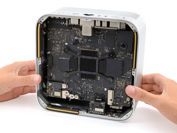
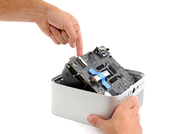
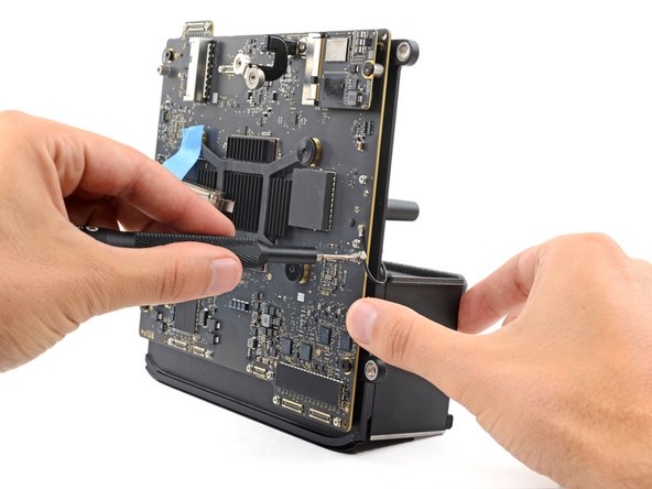
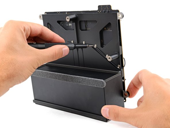
- With your free hand, carefully lift the edge of the logic board assembly with the SSD modules until you can grip the fans. Slide the assembly towards the power cord cutout as necessary to help you lift it higher.
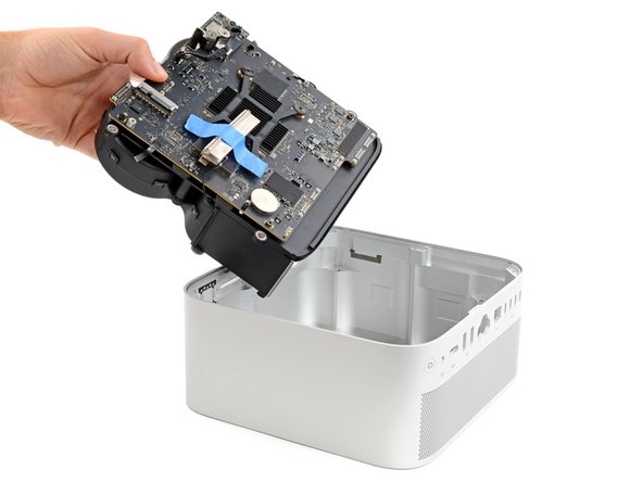
- Grip the board and fans together and lift the assembly out of its housing.
- Be careful not to damage any components on the edge of the assembly when removing it.
- During reassembly, lower the logic board assembly into its housing at a downward angle so the side with a rubber gasket is facing the power cord cutout.
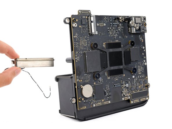
- Carefully stand up the logic board assembly so you can access the two fan cable connectors on the logic board.
- When the assembly is upright, make sure to secure it with your free hand as necessary. Otherwise, it may fall over and get damaged.
- Use tweezers to peel up the piece of tape covering one of the fan cable connectors.
- Use the point of a spudger or a clean fingernail to flip up the hinged locking flap on the fan cable ZIF connector.
- Use tweezers to gently pull the cable straight out of its socket and disconnect it.
- Repeat the previous two steps to disconnect the other fan cable.
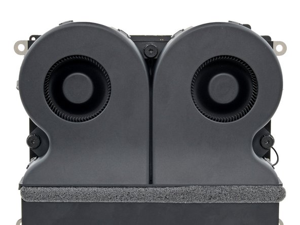
- Rotate the logic board assembly so the fans are facing you.
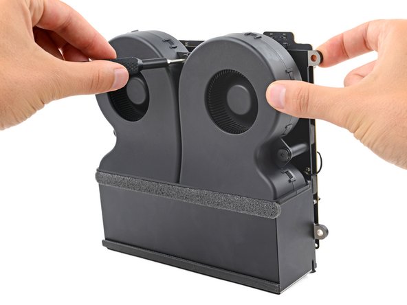
- Secure assembly with one hand.
- With your free hand, use a T10 Torx screwdriver to remove the three 10 mm‑long screws securing the fans.
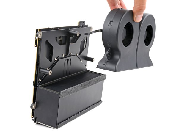
- Remove the fans.
- During reassembly, place the fans onto their screw posts with the fan cables facing the logic board assembly.
- Rotate the assembly so the logic board is facing you.
- Secure the assembly with one hand.
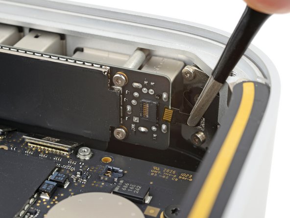
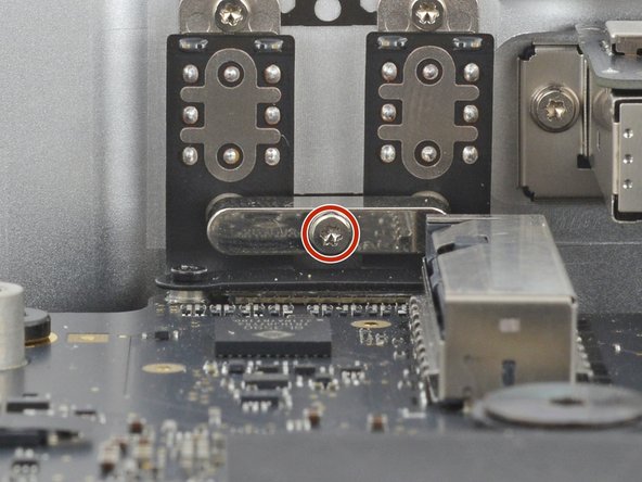
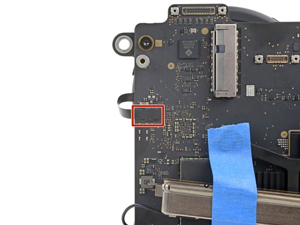
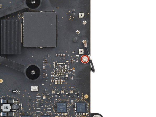
- With your free hand, use a T5 Torx screwdriver to remove the 2.9 mm‑long screw (with a washer) securing antenna 1's cable to the logic board.
- Be careful not to lose the washer.
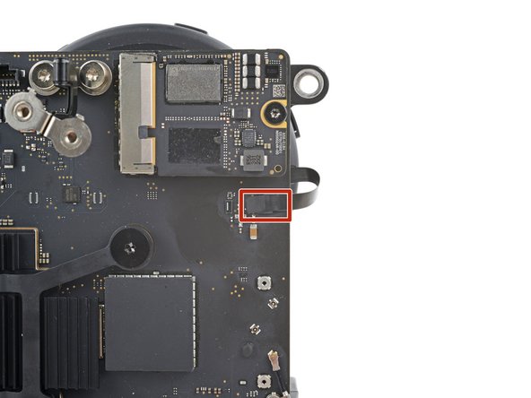
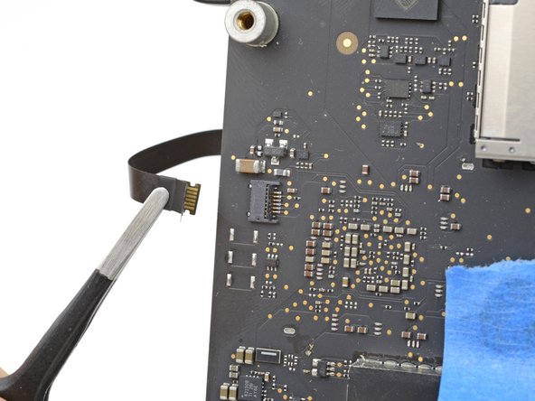
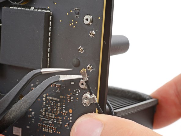
- Insert one arm of a pair of angled tweezers under the metal neck of antenna 1's coaxial connector and lift straight up to disconnect it.
- To reconnect the cable, hold the connector in place over its socket and press down with the flat end of a spudger—the connector should snap into place. If you're having trouble, don't try to force the connector over the socket. Reposition it and try again.
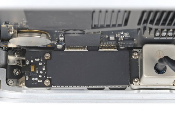
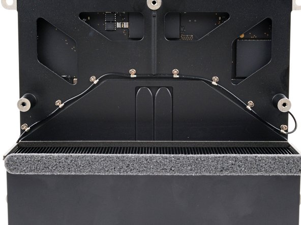
- Rotate the assembly so the logic board is facing away from you.
- Secure the logic board assembly with one hand.
- With your free hand, use a T5 Torx screwdriver to remove the eight 2.7 mm‑long screws securing antenna 1's cable to the logic board assembly.
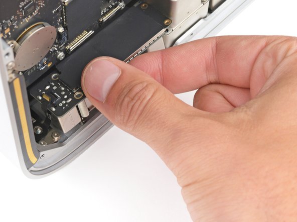
- Rotate the assembly so the logic board is facing you.
- Take the tape off antenna 1 and remove the antenna.