Yashica T5D Shutter Flex Cable Replacement
ID: 165372
Description: The Yashica T5(also known as Yashica T4 Super...
Steps:
- Install the battery, turn on the device, and wait for the lens to extend. Use rubber gloves or finger covers and gently unscrew the lens ring counterclockwise.
- Unscrew the three screws that secure the dust cover.
- After completion, turn off the device and make sure the lens retracts normally.
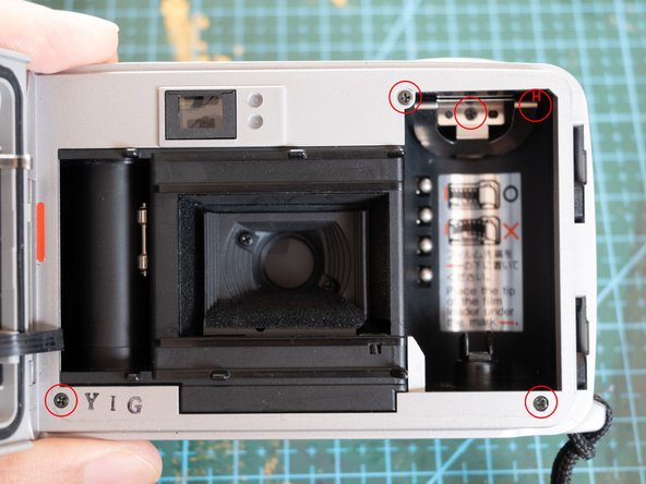
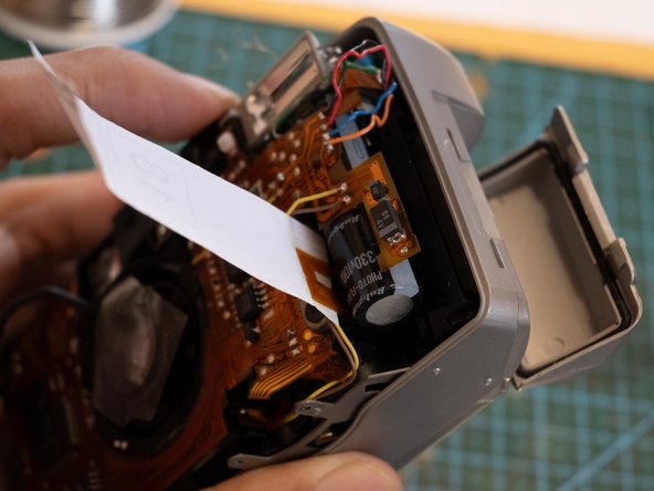
- Remove the battery and gently peel off the sticker in the battery compartment.
- For the D version camera, there is a ribbon cable underneath the sticker, so be careful to separate it gently.
- Unscrew the three screws inside the battery compartment.
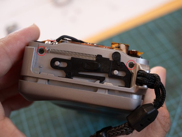
- Open the film compartment and unscrew the five screws, noting that one marked with an "H" is hidden under a spring clip. The screws are of different lengths and need to be labeled for reference when reinstalling them.
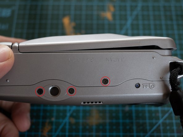
- Unscrew the three screws at the bottom.
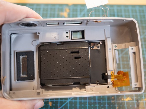
- There are several clips on the front cover that can be gently pried open using a plastic pry bar along the crevices. Slowly slide open the front cover.
- There is a line of waterproof rubber around the edge of the front cover, and wires are also present. When using tools, do not insert too deeply. (Please refer iPod disassembly for more information)
- Unsolder the four wires marked with No.1 yellow marker.
- Unsolder the four wires marked with No.2 marker.
- Unsolder the date cable with three contacts marked with No.3 marker.
- Unsolder the lens cable with three contacts marked with No.4 marker.
- Unsolder the button cable with three contacts (this machine may have been repaired in the past and used flying wires) marked with No.5 marker.
- Pull outwards to remove the left cover plate.
- Unscrew 2 screws.
- Gently lift the internal part from the right side. Be careful not to break the upper function cable (normal machines have soft cable, unlike mine) and date cable (date cable should bent and placed in the gap between the capacitor).
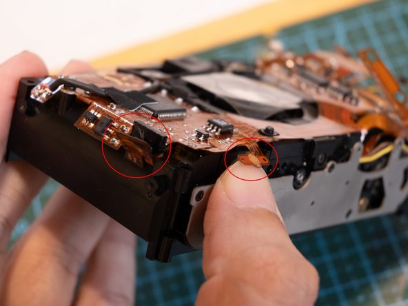
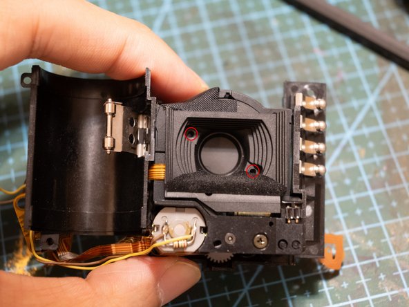
- Unscrew the 2 screws under the red circle, which are the two rows of wires used to connect the lens and the main board.
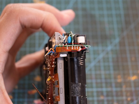
- Unsolder the 5 contacts that connect to the flash unit.
- Solder off the negative battery wire.
- Unscrew 2 screws.
- Solder off the positive battery wire.
- Takeoff the flash light/power module.
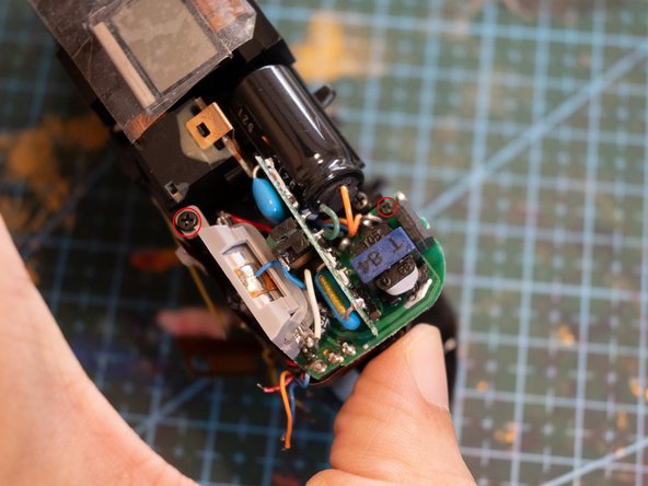
- Unscrew the screw labeled 5.
- Use a tool to remove solder from the contact with number 6.
- The double stick tape on the left is distributed in from 1 to 4.
- First gently remove the contacts of buttons 1 and 2 and take them off of the slot.
- Then use a tool to gently take off the main board with number 3.
- Note that there are also components on the back of the main board, so be careful not to break them.
- Now the main board should be lift like this.
- At this point, the mainboard and the viewfinder module are still connected together, and this part does not need to be disassembled. Is enough for replacing the lens cable.
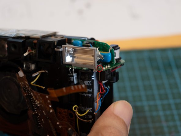
- Gently lift up the LCD screen and shutter button from both sides (be careful of the adhesive), unscrew the 2 screws marked.
- The viewfinder and main board can be completely take off.
- Unscrew the 6 screws, paying attention to the 2 screws on the side.
- Take off the lens module.
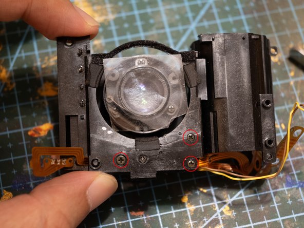
- Pic2: Unscrew the 2 screws, gently peel off the adhesive on the upper left corner, and remove the light shield.
- Pic3: Unscrew 3 screws to take off the lens and shutter module.
- This is Shutter FPC Cable.
- Use the resistance scale of a multimeter to test the five contacts and the gold fingers of the cable. If the resistance is infinite, it indicates that the cable is broken.
- Additionally, the two thin wires connected to the shutter motor at the bottom should be connected directly to the gold fingers and measure as continuous.
- Be mindful of the original cable's bend and installation position, and use double stick tape to secure it.
- Some parts require lubrication, so apply a small amount of grease.
- Avoid using a liquid lubricant to prevent it from seeping into the shutter and causing malfunction.
- When reassemble, follow the disassembly sequence (it is recommended to record a video to review and find any missed information such as how to place wire).
- For the date cable on the D version, you can use a strip of paper with adhesive on one end to pull it back.