Servicing the Nintendo Wii (RVL-001) disc drive
ID: 165531
Description: Hey Momo here showing you how to service and...
Steps:
- Disconnect all external cords from the Wii console.
- Gather all tools.
- One small screw holds the BIOS memory battery.
- Once that screw is removed, you can slide out the plastic slot.
- Remove these three black case screws. The one on the right is a few mm longer. These screws hold on the black plastic cover for the GameCube ports.
- Lift off the black plastic plate.
- There are four screws: two Phillips #00 and two Tri-Wing.
- Remove all screws from the case.
- Some screws are under rubber feet, or small, square paper screw covers (red square). I used a sharp metal tool to get under the screw covers. You could use an X-acto knife.
- Several case screws require a Tri-Wing screwdriver.
- The next step has more pictures of removing rubber feet and the screws underneath. The feet and screwcovers are self-adhesive, but not every foot or screwcover has a screw.
- Remove rubber feet and screws underneath.
- Careful! If you don't remove the feet and the screws underneath before you try to pull off the front panel, the tab can split!
- Once all screws are removed, you should be able to pull off the front drive panel.
- The wire connecting the front panel (green squares in the third image) can be pulled out gently by hand or with the help of a spudger.
- Now the case can be pulled apart.
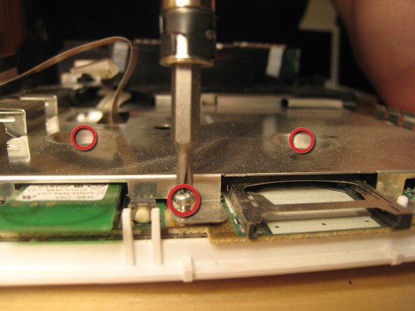
- We lifted up the cover of the optical drive by removing the six Phillips #00 screws. These are all labeled on the previous image.
- Because of a secured wire leading to the drive, we reattached the cover to facilitate the remove of the entire drive assembly without harming any of the electronics.
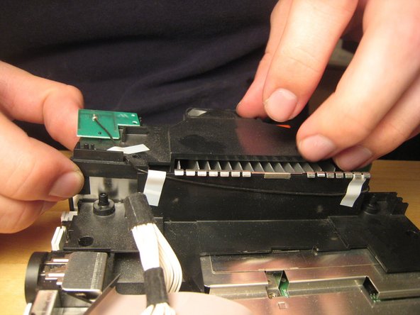
- There are a ton of parts in the optical drive, but there is nothing very fancy about this drive compared to other slot-loading drives, so I didn't take it apart completely. There are also a ton of gears and levers that I did not want to deal with.
- The screws holding in the drive were deep within the casing.
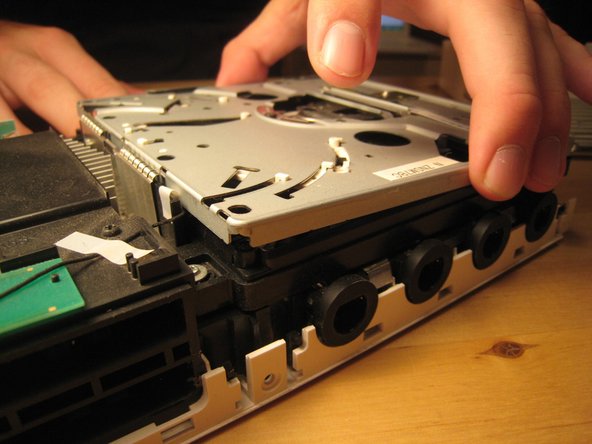
- Once those screws were removed, the entire case could be lifted off.
- Don't pull too hard! There are two cables attaching the drive to the logic board underneath.
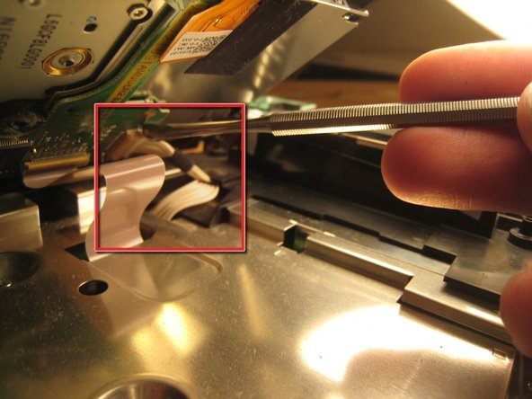
- This wire slid out from its horizontal slot. Once it was detached, the ribbon cable came out as well.
- With those wires detached, the optical drive came off completely.
- We begin trying to get to the logic board by removing this small black plastic rim.
- Once within the case, all screws are Phillips #00. There are marked on the logic board with arrows, triangles, boxes, and crosses. From what I can tell, an arrow means that it just goes through the logic board cover. A triangle means that it is a longer logic board cover screw. A cross means that it holds on a plastic piece, and a box means that it holds on another EM shield / or heat sink.
- Remove all screws from the logic board cover. Two are recessed in the middle; others are along the edge. More will become visible as other parts are removed. It's like a game! You can start with the screws holding in the black plastic pieces, but I started with the most visible and went from there.
- There are two wires (shown in the third picture) coming from the logic board and connected to the Wi-Fi antennas. These are delicate. Do not break them.
- Take out these screws in the black plastic casing.
- Detach the case fan. There are two screws holding it in.
- You must detach the power connector for the fan if you want to remove it completely.
- If your screwdriver is not magnetized, you will need a magnet to get out some of the embedded screws. You can hold a magnet against your screwdriver shaft to temporarily magnetize it.
- Once all the screws out, you can begin to remove the black casing.
- With the black plastic covers off, we can see all the screw holes. Most of the screws are out by now, but once the rest of them are out, you can lift off the logic board cover.
- Note that at least one part is thermal padded to the logic board cover. You might have to replace this thermal pad, but I didn't. I just pushed them back together. Oh well!
- Remove any remaining screws in the logic board cover.
- Once all screws are removed, lift off the logic board cover.
- Look around.
- This is the thermal padding.
- We opted not to remove the heat sink from the logic board, but it certainly could be removed.
- Take some more awesome photos.
- And take a couple more photos.
- We stopped there.
- A muffin tin worked really well to organize all the screws.
- Putting the Wii back together took only about half an hour, and it works perfectly. We improved Nintendo's design by three or four screws and one square nut, but worsened their design by one piece of duct tape (to hold in the bios battery).