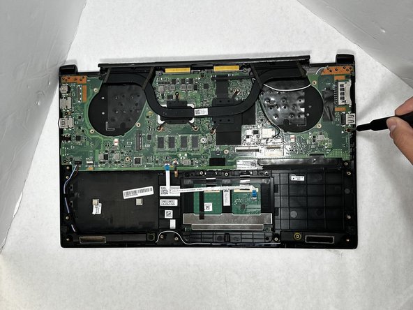
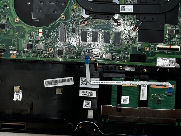
ASUS Q536F Motherboard Replacement
ID: 167129
Description: When replacing a motherboard, it's crucial to...
Steps:
- Remove ten 2 mm screws using a Phillips #0 screwdriver.
- Remove the screw in the center using a T4 Torx screwdriver.
- Use an iFixit opening tool to pry open the back panel.
- It's normal to hear some cracking, but proceed with caution.
- Remove the four 2 mm screws from the battery using a Phillips #1 screwdriver.
- Detach the battery cable from the motherboard using a pair of tweezers.
- Unhinge the fan cable using your fingers or a pair of tweezers.
- Remove the battery from its slot.
- There should be no resistance from any cable wiring at this point. If there happens to be resistance, make sure to double check and confirm nothing is being pulled.
- Use a Phillips #0 screwdriver to remove the six 2 mm fan screws.
- Use a Phillips #0 screwdriver to remove the five 2 mm heatsink screws.
- Warped Screw
- Heatsink shown has warped screw, so unable to remove
- Disconnect white and black antennae cables.
- Using tweezers for this would be helpful.
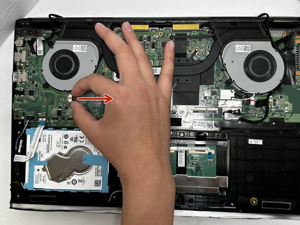
- Disconnect fan cables pulling outwards as shown.
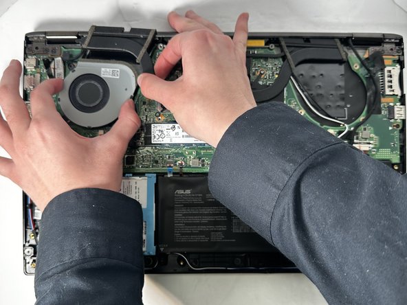
- Carefully lift heatsink upward using a Ifixit opening tool or Fingers pull fan out from under the heat sink.
- The fan can be removed without removing the heatsink, although it may be easier to remove.
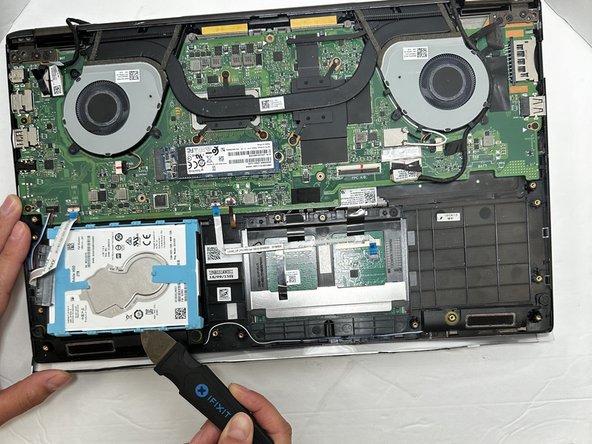
- Disconnect the white ribbon cable from the connection lever using a Jimmy.
- Using the Jimmy, lift the hard drive out of its slot.
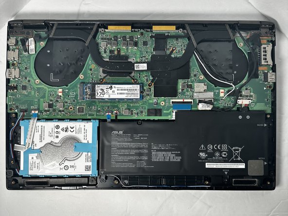
- Remove the single 2 mm screw from the SSD with a Phillips #0 screwdriver.
- Pull the SSD out of its slot.
- Use a Phillips #0 screwdriver to remove the four 2 mm screws that secure the motherboard.
- Using a Jimmy, pull up on the power cable.
- Using the Jimmy, lift up on both ribbon cable clamps, releasing the connection point, just like in step 8.