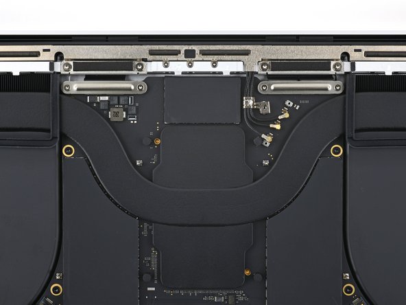
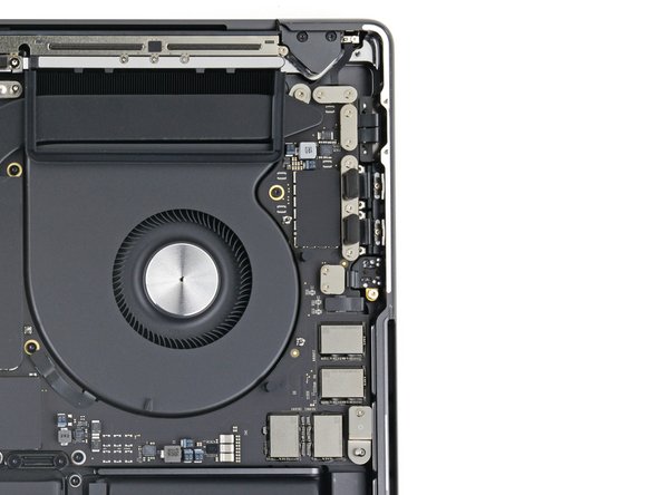
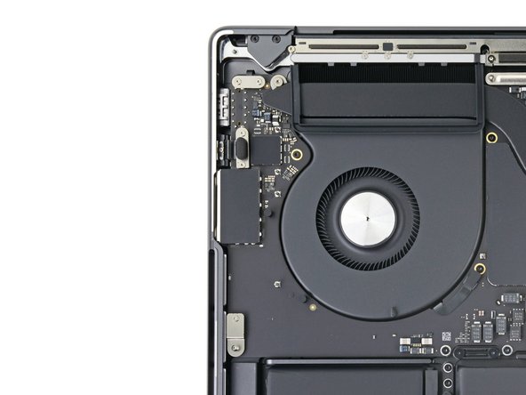
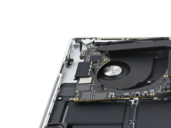
MacBook Pro 16" Late 2023 Speakers Replacement
ID: 167359
Description: Use this guide to replace one or both speakers...
Steps:
- Allow your MacBook's battery to drain below 10% before starting this repair. A charged battery may catch fire if damaged during the repair.
- Fully shut down your MacBook, close the lid, and flip it over. Keep the lid closed until you've physically disconnected the battery.
- Unplug the MagSafe cable and any accessories connected to your MacBook.
- Completely power off and unplug your MacBook Pro before you start. Close the screen and flip the entire laptop upside-down.
- Use a P5 Pentalobe driver to remove eight screws securing the lower case:
- Four 9.2 mm screws
- Four 5 mm screws
- Throughout this repair, keep track of each screw and make sure it goes back exactly where it came from to avoid damaging your device.
- Press a suction handle into place near the front edge of the lower case, between the screw holes.
- Pull up on the suction handle to create a small gap under the lower case.
- Insert an opening pick into the gap you just created.
- Slide the opening pick around the nearest corner and then halfway up the side of the MacBook Pro.
- This releases the first of the hidden clips securing the lower case. You should feel and hear the clip pop free.
- Repeat the previous step on the other side, using an opening pick to to release the second clip.
- Sliding clips along the back edge of the MacBook further secure the lower case. Separating these clips may require a lot of force—consider using gloves to protect your hands from the sharp edges of the lower case.
- Firmly pull the lower case away from the back edge, one corner at a time, to disengage the sliding clips.
- Keep the lower case flat to the MacBook. Don't pull upward until it's completely separated.
- Remove the lower case.
- To reinstall the lower case:
- Set it in place and align the sliding clips near the screen hinge. Press down and slide the cover toward the hinge. It should stop sliding as the clips engage.
- When the sliding clips are fully engaged and the lower case looks correctly aligned, press down firmly on the lower case to engage the four hidden clips underneath. You should feel and hear them snap into place.
- Peel back any tape covering the battery board data cable connector on the logic board.
- Use a spudger to gently pry up the locking flap on the ZIF connector for the battery board data cable.
- Disconnect the battery board data cable by sliding it out from its socket on the logic board.
- Use a 3IP Torx Plus driver to remove the two 2.1 mm‑long screws securing the trackpad cable bracket to the logic board.
- Use tweezers, or your fingers, to remove the trackpad cable bracket.
- Use the flat end of a spudger to pry up and disconnect the trackpad cable's press connector from the logic board.
- To re-attach press connectors like this one, carefully align and press down on one side until it clicks into place, then repeat on the other side. Do not press down on the middle. If the connector is misaligned, the pins can bend, causing permanent damage.
- The trackpad cable is lightly adhered to the frame.
- Peel the trackpad cable away from the device, making sure to separate the adhesive.
- Peel back any tape covering the battery board data cable connector under the large pancake screw.
- Use a spudger to gently pry up the locking flap on the ZIF connector for the battery board data cable.
- Disconnect the battery board data cable by sliding it out from its socket on the battery board.
- The battery board data cable is lightly adhered to the device.
- Slide blunt nose tweezers under areas with adhesive to separate the cable from the device.
- Remove the battery board data cable.
- Use a 5IP Torx Plus driver to remove the 4 mm pancake screw securing the battery power connector.
- Use the flat end of your spudger to lift the battery connector away from the battery board, disconnecting the battery.
- Lift the connector high enough that it doesn't accidentally make contact during the repair, but no more than 45 degrees to prevent damaging its hinge.
- For added safety, place a barrier, such as a piece of a playing card, between the connector and board.
- Use a 3IP Torx Plus screwdriver to remove the three 2.1 mm screws securing the antenna bar bracket and coaxial cable cover to the frame.
- Use tweezers, or your fingers, to remove the cover on top of the antenna bar's coaxial cables.
- Use the tip of a spudger to pry up and disconnect the antenna bar's coaxial cable.
- Repeat for the two other cables.
- During reassembly, these can be tricky to reconnect. Hold each connector in place over its socket and press down with the flat end of a spudger. The connector should snap into place.
- Use a 3IP Torx Plus driver to remove the four 3.5 mm screws securing the screen cable covers.
- Use tweezers, or your fingers, to remove the two screen cable covers from the logic board.
- Use the flat end of a spudger to pry up and disconnect the two right-most screen cable press connectors secured to the logic board.
- Repeat the previous disconnection process for the remaining press connector at the top left of the logic board.
- Don't pry against the surface-mounted components near the press connector.
- Peel back any tape covering the microphone cable connector.
- Use a spudger to gently pry up the locking flap on the ZIF connector for the microphone cable.
- Disconnect the microphone cable by sliding it out from its socket on the logic board.
- Use a 3IP Torx driver to remove the 11 screws securing the right cable covers to the frame:
- Ten 2.1 mm screws
- One 3.6 mm screw
- Use tweezers, or your fingers, to remove the five right cable covers.
- Use the flat end of a spudger to pry up and disconnect the right speaker's press connector.
- Use a spudger to pry up and disconnect the headphone jack's press connector.
- Use a spudger to pry up and disconnect the right USB-C ports' two press connectors.
- Use a spudger to pry up and disconnect the MagSafe port's press connector.
- Use a spudger to pry up and disconnect the lid angle sensor's press connector.
- Use a 3IP Torx Plus driver to remove the six screws securing the left cable covers to the frame:
- Five 2.1 mm screws
- One 3.6 mm screw
- Use tweezers, or your fingers, to remove the three left cable covers.
- Use the flat end of a spudger to pry up and disconnect the left speaker's press connector.
- Use a spudger to pry up and disconnect the left USB-C port's press connector.
- Use a spudger to pry up and disconnect the Touch ID sensor's press connector.
- Peel back any tape covering the keyboard and keyboard backlight cable connectors.
- Use a spudger to gently pry up the locking flap on the two ZIF connectors for the keyboard cables.
- Disconnect the keyboard and keyboard backlight cables by sliding them out from their sockets on the logic board.
- Peel back any tape covering the right fan cable connector.
- Use a spudger to gently pry up the locking flap on the ZIF connector for the right fan cable.
- Disconnect the right fan cable by sliding it out from its socket on the logic board.
- The right fan cable is lightly adhered to the logic board.
- Use tweezers to pull the fan cable away from the logic board and separate the adhesive.
- The fan cables are incredibly delicate and prone to tearing; use caution when bending them with tools.
- Repeat the previous disconnection and reposition procedure for the left fan cable.
- Use a 5IP Torx driver to remove the ten screws securing the logic board to the frame:
- Six 3.9 mm screws
- Four 4.7 mm screws
- Use a 4 mm Hex driver to remove the two 6 mm screws securing the logic board to the frame.
- Use a T6 Torx driver to remove the two 6 mm screws securing the heat sink to the logic board and frame.
- Insert a spudger between the right side of the logic board and the frame.
- Pry up with the spudger to release the logic board from its clips.
- Insert a spudger between the bottom of the logic board and the frame.
- Pry up with the spudger to release the logic board from its clips.
- Gently lift up the logic board by its right side to release it from its alignment pegs.
- If it feels like it's not coming out, check that all the cables are disconnected.
- Pull the logic board away from the left side of the device to separate the HDMI and SDXC ports from their slots in the frame.
- Remove the logic board.
- During reassembly, perform the following:
- Make sure all 17 connectors are above the logic board before securing it back into the frame.
- If you're having trouble positioning the connectors, use tape to keep them out of the way.
- Hold the rubber spacers out of the way so the fins can drop into their recesses.
- When reinstalling the logic board, insert the left side first to reposition the HMDI and SDXC ports.
- Use your fingers to slightly compress the HDMI port to fit it into its recess. Otherwise, the logic board won't sit correctly.
- Use a spudger to remove the four screw covers.
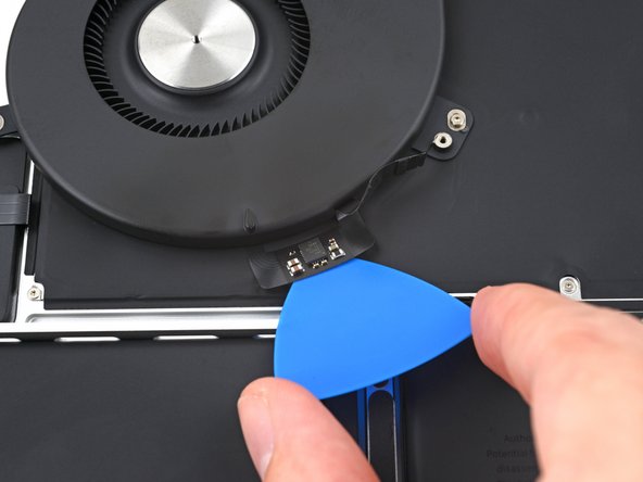
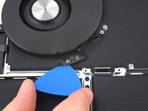
- Both of the fans' cables are lightly adhered to the frame.
- Insert the tip of an opening pick between the fan's cable and the frame.
- Slice with the pick along the edges of the cable to separate the adhesive.
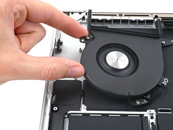
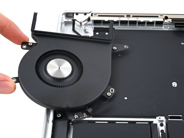
- Remove the eight screws securing the fans to the frame:
- Four 3.3 mm 3IP Torx Plus screws
- Four 3 mm 5IP Torx Plus screws
- Remove the fans.
- Use a 5IP Torx Plus driver to remove the 13 screws securing the trackpad assembly:
- Ten 5 mm screws
- Three 5.8 mm screws
- These screws all look similar—be careful not to mix them up.
- Adding a little blue threadlocker to the screw threads during reassembly can help prevent the screws from working themselves loose over time.
- Install the screws loosely at first, and then check the trackpad alignment before tightening them down.
- Swing the display open slightly, but keep the MacBook upside-down. The trackpad assembly should separate and lay flat on the display.
- Carefully feed the trackpad's ribbon cable through its slot in the frame.
- As you remove the trackpad assembly, be very careful not to lose the nine small metal washers resting on the screw posts. (They will fly off and get lost with very little provocation.)
- Remove the trackpad assembly.
- Use a 5IP Torx Plus driver to remove the two screws securing the battery board:
- One 4.5 mm screw
- One 3.8 mm screw
- There are 14 total stretch release adhesive strips that secure the battery to the frame:
- There are eight adhesive strips that are accessed from the bottom of the device.
- There are six more adhesive strips accessed from the trackpad's location on the frame.
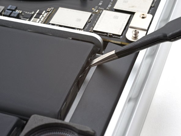
- Use tweezers, or your fingers, to grasp the black pull-tab on one of the adhesive strips.
- Pull the strip out slowly and steadily at a low angle. Give it plenty of time to stretch and un-stick from under the battery.
- If the adhesive strip breaks off, try to retrieve it using your fingers or blunt tweezers, and continue pulling—but do not pry under the battery.
- Repeat the process for all 14 stretch release adhesive strips.
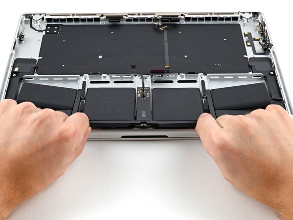
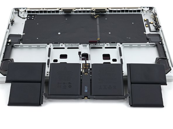
- Slide the battery out of the frame to remove it.
- During reassembly, apply new stretch-release adhesive to your battery and press each cell into place.
- Alternatively, you may use strong double-sided tape such as Tesa Tape to secure the battery.
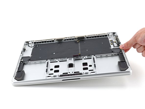
- Apply a few drops of highly-concentrated isopropyl alcohol (>90%) along the inside edges of the speaker.
- Tilt the right edge of the device upward to allow the isopropyl alcohol to work its way underneath the speaker.
- Hold for 1–2 minutes to allow time for the isopropyl alcohol to weaken the adhesive.
- While you're waiting for the adhesive to loosen, note where the adhesive is located underneath the speaker.
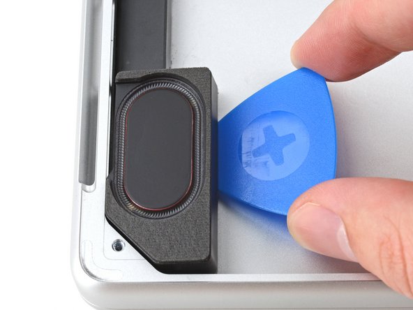
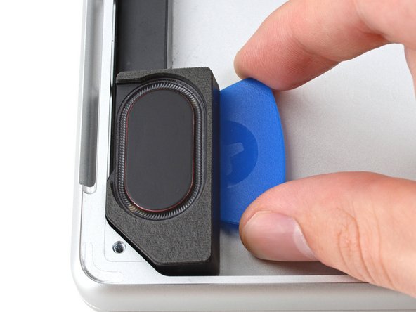
- Insert the tip of an opening pick between the bottom of the speaker and the frame.
- Slide the pick upwards to separate the adhesive along the bottom length of the speaker.
- Leave the pick in to prevent the adhesive from resealing.
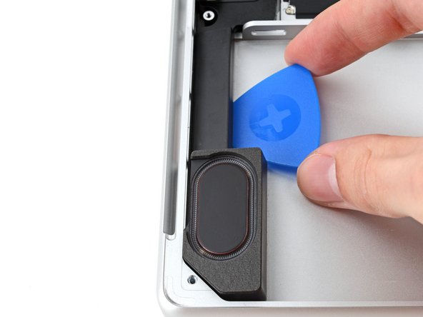
- Insert the tip of an opening pick between the top of the speaker and the frame.
- Pry up with the pick to completely separate the top adhesive.
- Remove the speaker.
- If you're still feeling resistance, slice along the perimeter of the speaker or apply a few more drops of isopropyl alcohol.
- Repeat the loosening and separating process for the other speaker.
- If any adhesive remains, clean it with a few drops of isopropyl alcohol and wipe it with a lint-free or microfiber cloth.