Abask J05 Camera Replacement
ID: 167382
Description: This is a step-by-step guide to replace the...
Steps:
- Gently press on the SD card with a fingernail until it clicks.
- Release, then remove the card.
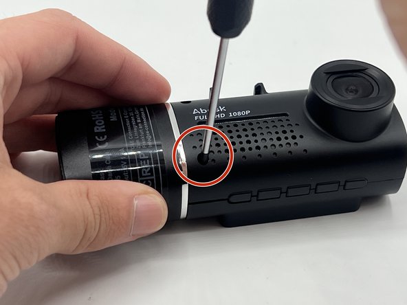
- Remove the 5 mm screw from the side of the device next to the suction cup dock with a Phillips #00 screwdriver.
- Remove the two 8 mm screws from opposite sides of the screen with a Phillips #00 precision screwdriver.
- Gently lift the screen.
- Push up on the interior camera portion of the device. It should pop out of the socket. Being careful to keep the wires attached, set it to the side.
- Reach into the device with a spudger to release the top two snap joints keeping the end cap attached one at a time until the front face lifts off.
- Be careful not to touch the screen.
- Repeat the process with the two remaining snap joints.
- Remove the two 7 mm screws on the side of the motherboard with a Phillips #00 screwdriver.
- Slowly pull up on each corner of the motherboard, stopping when the corner pops loose of the anchor.
- Repeat the process with each corner before slowly pulling up on the board to detach the glue on the underside.
- Move the motherboard aside, and peel off the tape over the small black plastic piece.
- Remove the two 8 mm screws with a Phillips #000 screwdriver.
- Remove the two 5 mm screws using a Phillips #00 screwdriver.
- Remove the camera.