LG Refrigerator Water Inlet Valve Assembly Test and Replacement
ID: 167680
Description: Use this guide to replace the water inlet valve...
Steps:
- Unplug your refrigerator before you begin your repair.
- If you are testing or repairing the following items, you may also need to shut off and disconnect the water supply:
- Condenser fan motor
- Compressor motor and thermal overload device
- Water supply valve assembly
- Use a Phillips screwdriver to remove the screws securing the condenser cover to the rear of the refrigerator.
- Tilt the top edge of the condenser cover toward you.
- Lift and remove the condenser cover.
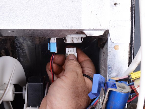
- Squeeze and pull down the connectors for the valve assembly harness to disconnect them.
- Use a Phillips screwdriver to remove the screw(s) securing the water inlet valve assembly.
- Pull the water inlet valve assembly out of the refrigerator for better access to electrical connections and water tubing connections.
- Don't try to remove the inlet valve assembly completely because it is still attached by tubes and wires.
- Squeeze and pull downward the remaining water inlet valve assembly connector(s) to disconnect it.
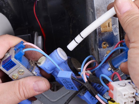
- Use long nose pliers to pull and remove the locking clip from a tubing connector.
- Use your fingers to squeeze the flange surrounding the water tube toward the valve to release the tube.
- While you squeeze the flange, pull the tubing straight out of the connector.
- Repeat this procedure for the remaining tubes.
- Remove the inlet valve assembly.
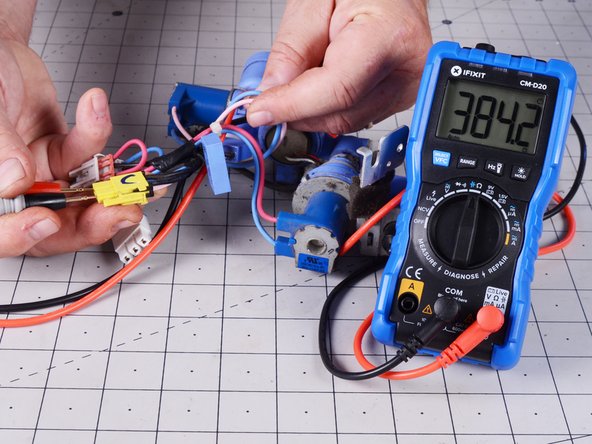
- If you have a multimeter, you can use it to test the inlet valve assembly components.
- Set the multimeter to the ohm (Ω) setting.
- For the first solenoid, test the resistance between the wires from it at the connector.
- The acceptable resistance is 360 to 420 Ω.
- Repeat the test on the connector for the other solenoid.
- The acceptable resistance is 360 to 420 Ω.
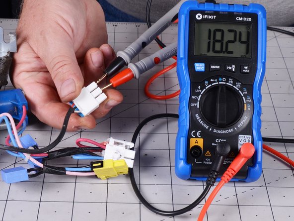
- To test the flow meter, test the resistance between the wires from it at the connector.
- The acceptable resistance is 4 kΩ to 30 kΩ.