MacBook Pro 14" Late 2023 (M3) Headphone Jack Replacement
ID: 167786
Description: Use this guide to replace a broken or faulty...
Steps:
- Allow your MacBook's battery to drain below 25% before starting this repair. A charged battery may catch fire if damaged during the repair.
- Fully shut down your MacBook, close the lid, and flip it over. Keep the lid closed until you've physically disconnected the battery.
- Unplug the MagSafe cable and any accessories connected to your MacBook.
- Throughout this repair, keep track of each screw and make sure it goes back exactly where it came from.
- Use a P5 pentalobe driver to remove the eight screws securing the lower case:
- Four 9.2 mm-long screws along the back edge (near the screen hinge)
- Four 5 mm-long screws along the front edge (near the trackpad)
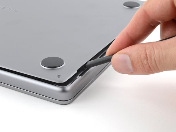
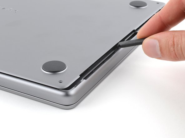
- Sliding clips along the back edge of the MacBook secure the lower case. In this step, you'll shift the lower case away from the hinges to free it from these clips.
- Insert the flat end of a spudger between the lower case and the right screen hinge.
- Lever your spudger against the hinge to push the lower case away from it.
- Repeat for the left hinge.
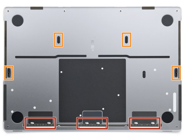
- After you've released the sliding clips along the back edge, four remaining clips secure the lower case to the frame:
- Two clips near the cutouts in the frame
- Two clips near the middle of the lower case
- As you release the lower case from the frame, you'll hear and feel a distinct "pop" as each of these four clips release.
- Don't insert your tool deeper than 1 cm (a little less than half an inch) near the front of the speaker cutouts to avoid damaging the speakers.
- Insert the flat end of your spudger into the front of the cutout in the right side of the frame.
- Slide your spudger toward the back of the cutout and pry up to release the two right-side clips.
- Repeat for the left-side speaker cutout to release the two left-side clips.
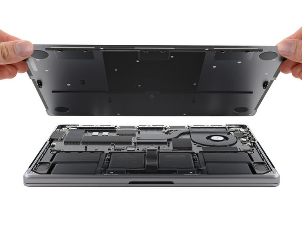
- Remove the lower case.
- To reinstall the lower case:
- Lay it down and align the sliding clips with the back edge of the MacBook. Press down on the lower case and slide it toward the back edge to engage the clips.
- When one side is engaged, it may push the other out of alignment. Check both sides as you push.
- Once the back corners of the lower case are secured and flush with the frame, press down along the middle of the lower case to engage the four remaining clips.
- You'll hear and feel each clip snap into place.
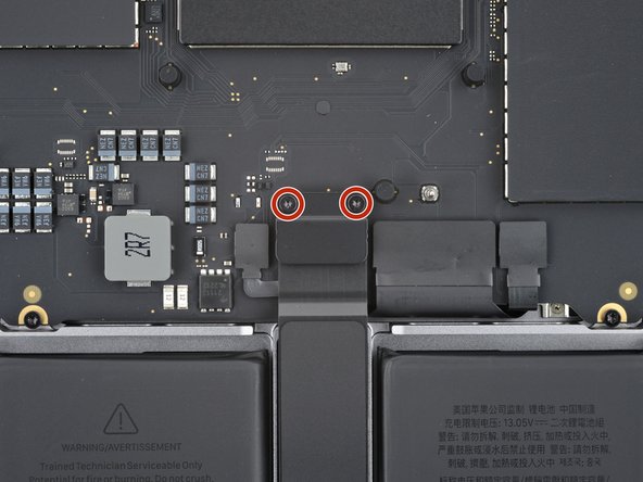
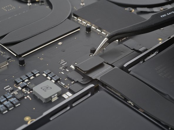
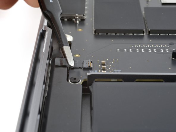
- Use a 3IP Torx Plus driver to remove the two 2.1 mm-long screws securing the trackpad connector cover.
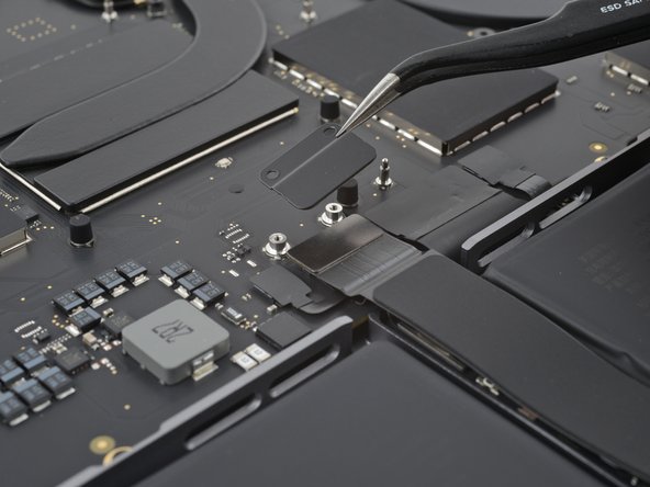
- Remove the trackpad connector cover.
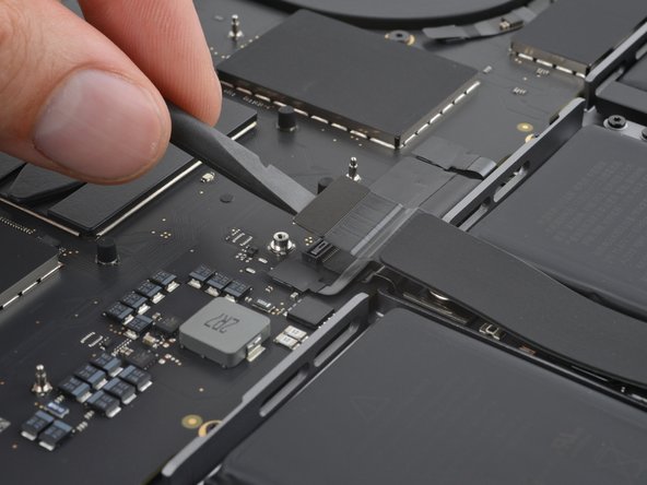
- Use the flat end of your spudger to pry up and disconnect the trackpad press connector from the logic board.
- To re-attach press connectors like this one, carefully align and press down on one side until it clicks into place, then repeat on the other side. Don't force it, since a misaligned connector can bend the pins, and cause permanent damage.
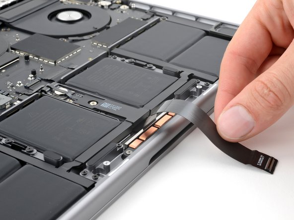
- Light adhesive secures the trackpad cable to the battery board.
- Peel the trackpad cable from the battery board and move it over the front edge of the MacBook.
- Be careful not to crease or damage the cable.
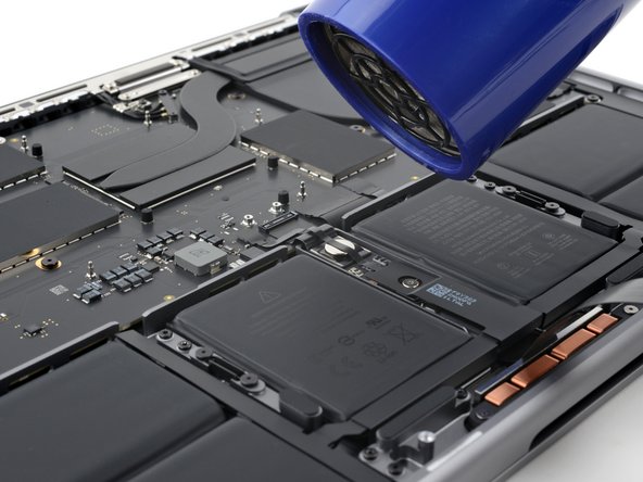
- The battery data cable is adhered to the battery board and logic board. In the next few steps, you'll disconnect it, separate its adhesive, and remove it.
- Heat an iOpener and place it on the battery data cable for 30 seconds to soften its adhesive.
- If you don't have an iOpener, you can use a hair dryer to lightly heat the cable. Be careful not to overheat the battery, as doing so is a fire hazard.
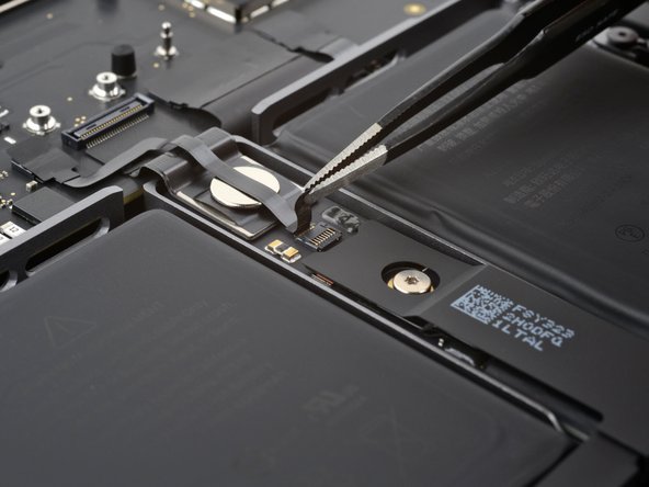
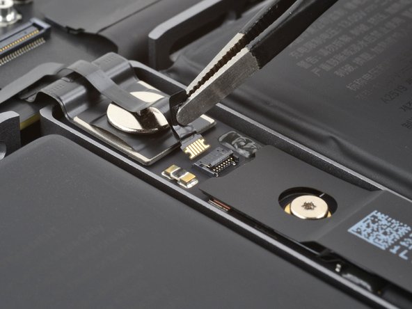
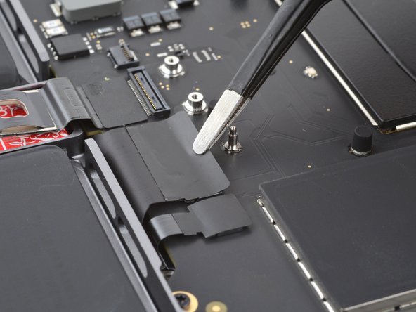
- Use your tweezers to peel back the tape covering the battery data cable ZIF connector on the battery board.
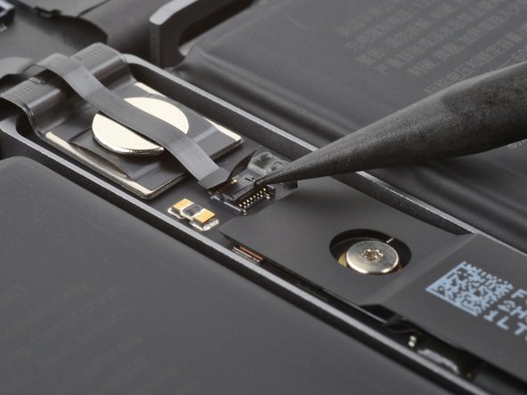
- Use the point of your spudger to flip up the small locking flap on the battery data cable ZIF connector on the battery board.
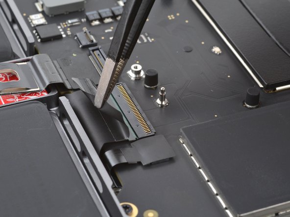
- Use your tweezers to slide the connector straight out of its socket to disconnect it from the battery board.
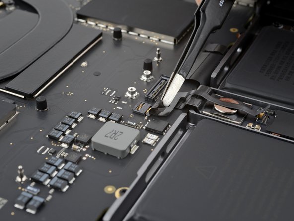
- Use your tweezers to peel back the tape covering the battery data cable ZIF connector on the logic board.
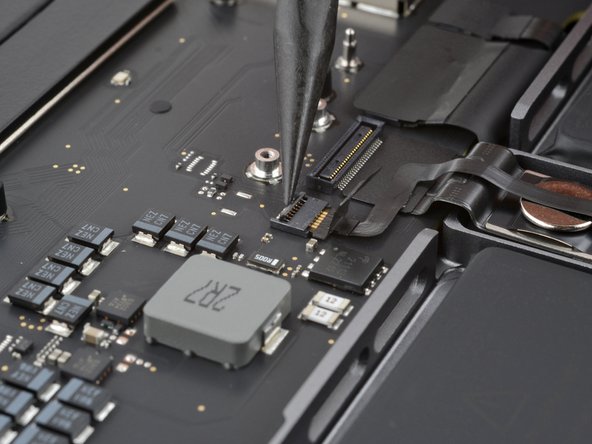
- Use the point of your spudger to flip up the small locking flap on the logic board battery data ZIF connector.
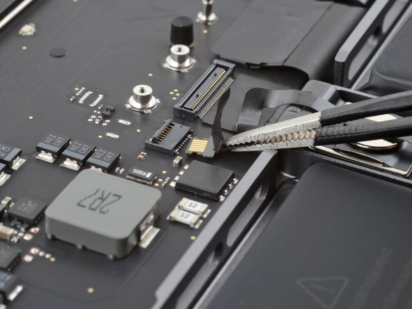
- Use your tweezers to grip the neck of the cable and slide it straight out of its socket to disconnect it from the logic board.
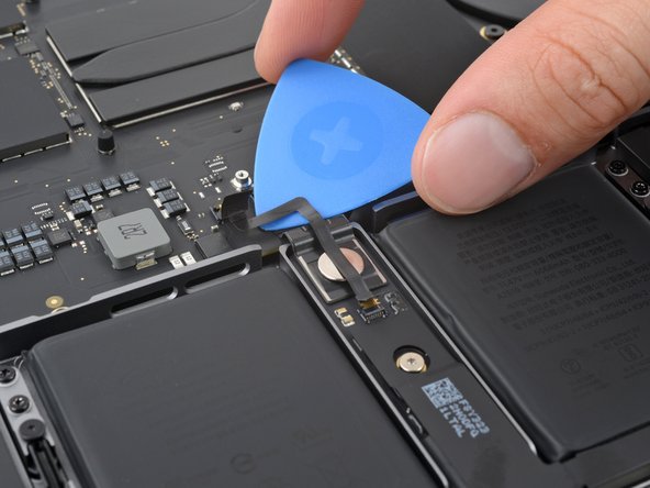
- The battery data cable is lightly adhered to the battery board and logic board.
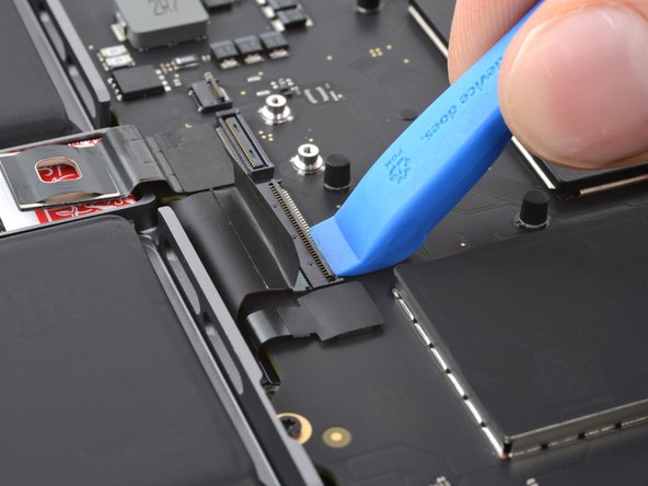
- Slide the tip of an opening pick between the upper section of the battery data cable and the logic board to separate the adhesive.
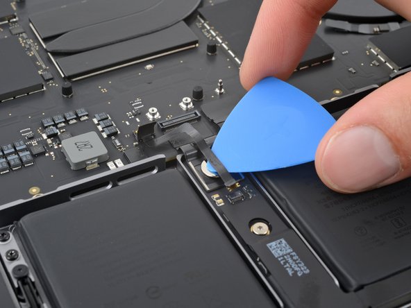
- Slide your pick between the lower section of the cable and the silver wide-head screw to separate the remaining adhesive.
- Remove the battery data cable.
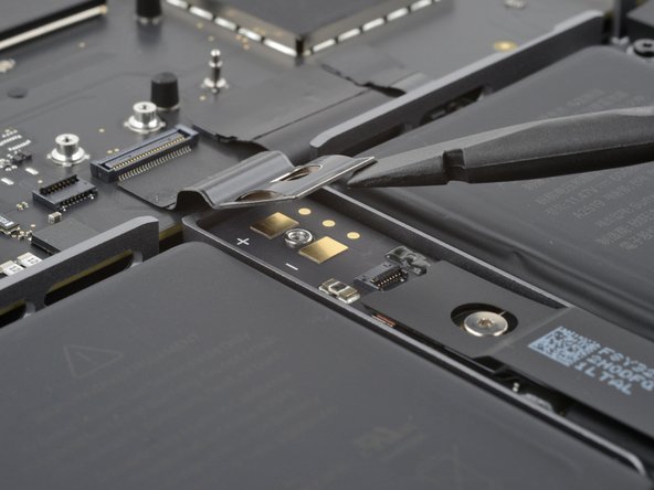
- Use a 5IP Torx Plus driver to remove the 3.9 mm-long wide-head screw securing the main battery connector.
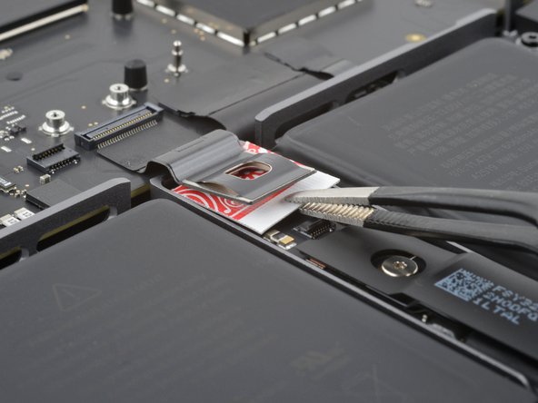
- Use the flat end of your spudger to lift the main battery connector away from the battery board, disconnecting the battery.
- Lift the connector high enough that it doesn't accidentally make contact during the repair, but no more than 45 degrees to prevent breaking it.
- For added safety, place a non-conductive barrier, such as a piece of a playing card, between the connector and board.
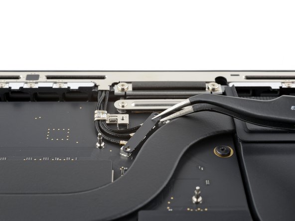
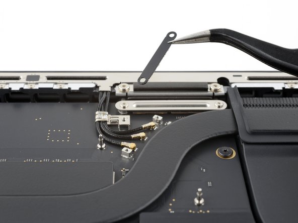
- Use your 3IP Torx Plus driver to remove the three 2.1 mm-long screws securing the antenna connector cover and bracket.
- Remove the cover.
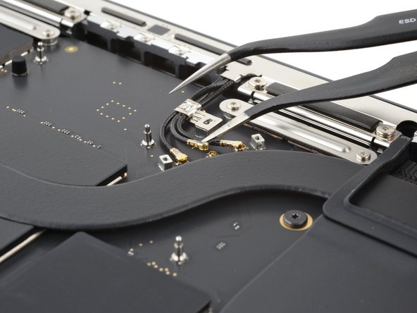
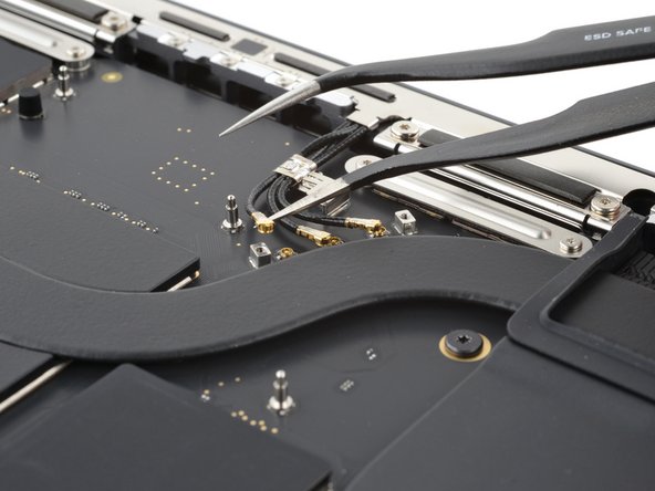
- Insert one arm of your angled tweezers under the metal neck of one of the antenna connectors and gently lift up to disconnect it.
- Lift only on the metal sections of the connectors. Don't lift the cables themselves.
- Repeat for the other two antenna connectors.
- To reconnect antenna cables like these, hold each one in place over its socket and press down with the flat end of your spudger until the connector snaps into place.
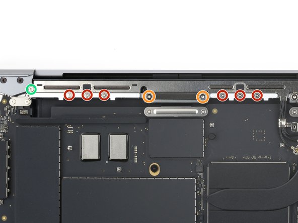
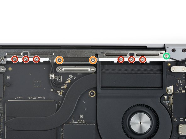
- Use a P2 pentalobe driver to remove the nine 1.6 mm-long screws securing the antenna bar.
- During reassembly, don't overtighten these screws—ensure they thread in properly, then tighten only until they're snug.
- Use your 5IP Torx Plus driver to remove the six remaining screws securing the antenna bar:
- Four 3.2 mm-long screws
- Two 7.5 mm-long screws
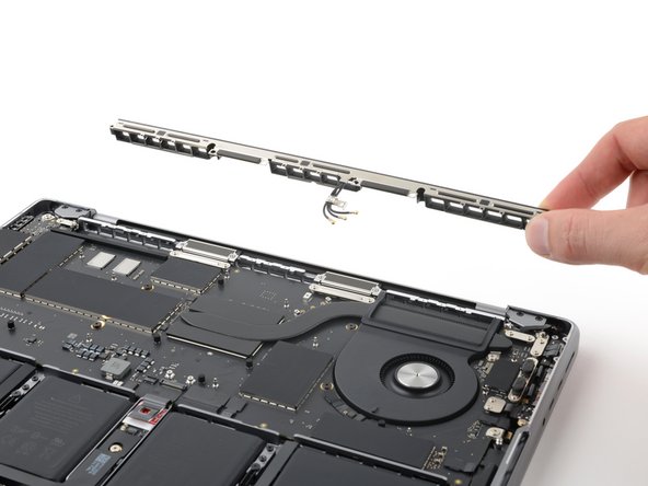
- Remove the antenna bar.
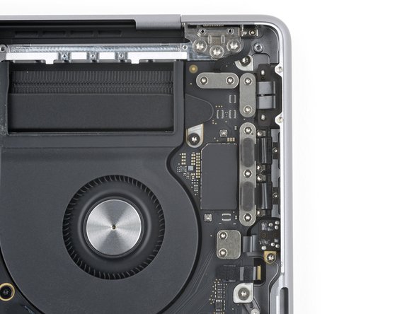
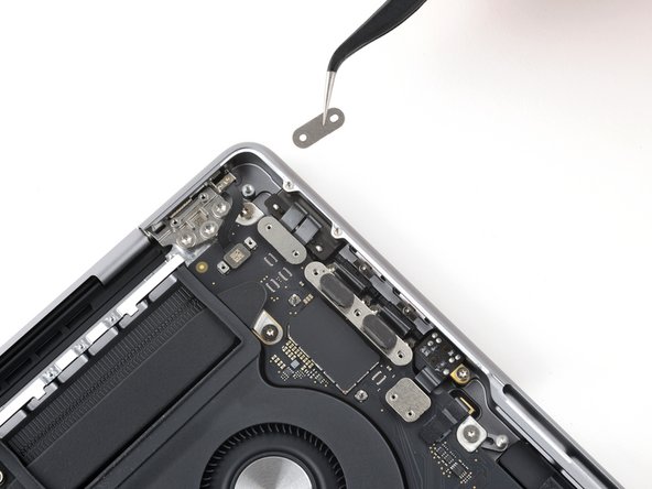
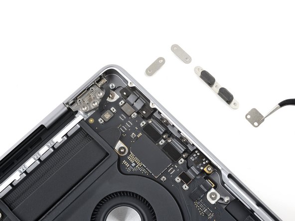
- Use your 3IP Torx driver to remove the nine 2.1 mm-long screws securing the four connector covers to the right side of the logic board.
- Use tweezers or your fingers to remove the four connector covers from the right side of the logic board.
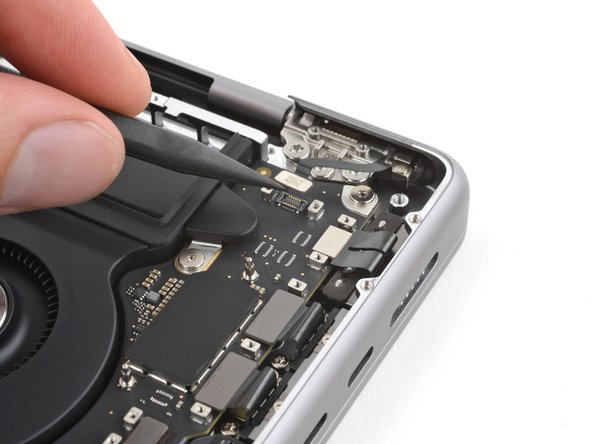
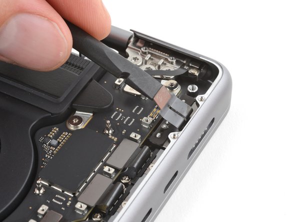
- Use the point of your spudger to pry up and disconnect the lid angle sensor press connector.
- Use the flat end of your spudger to pry up and disconnect the MagSafe port press connector.
- Use the flat end of your spudger to pry up and disconnect the two USB-C port press connectors.
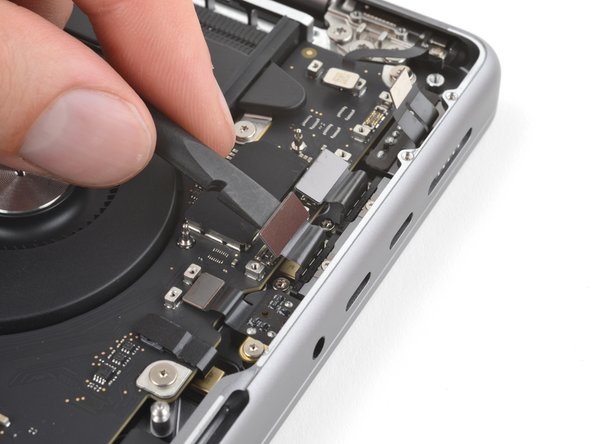
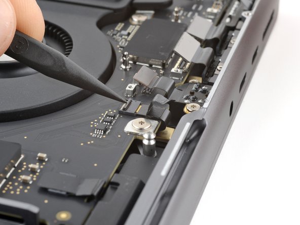
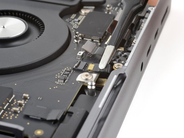
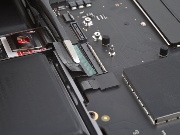
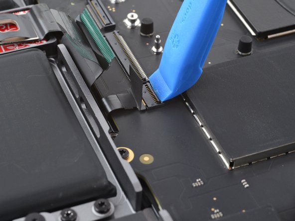
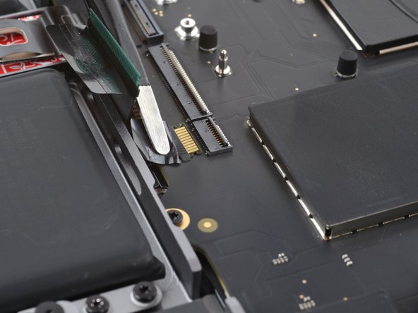
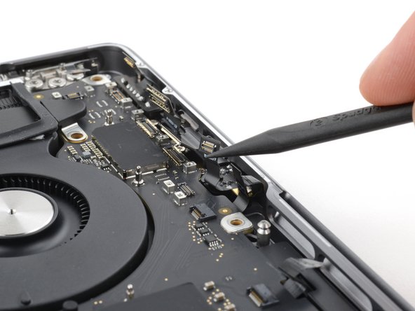
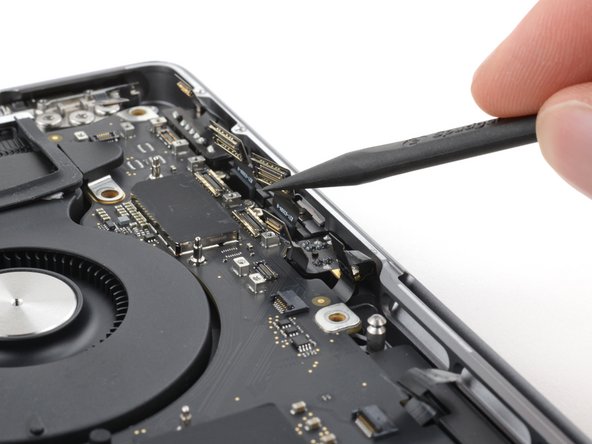
- Use the point of your spudger to pry up and disconnect the headphone jack press connector.
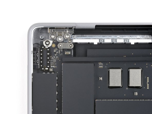
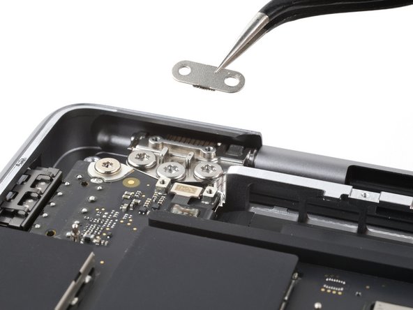
- Use your 3IP Torx Plus driver to remove the two 2 mm-long screws securing the touch ID connector cover to the top left corner of the logic board.
- Remove the touch ID connector cover.
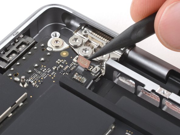
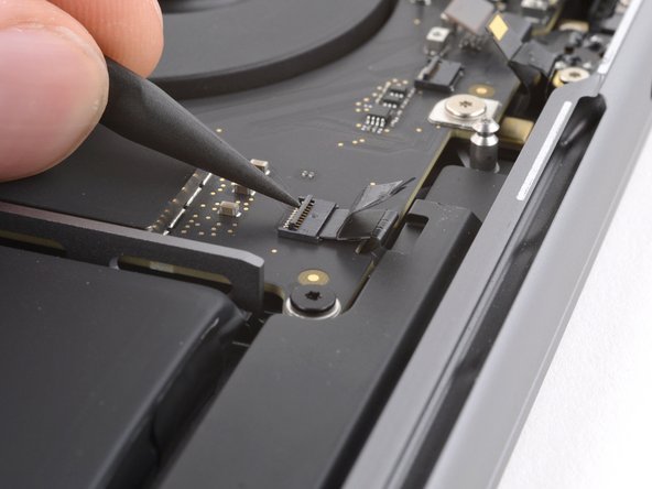
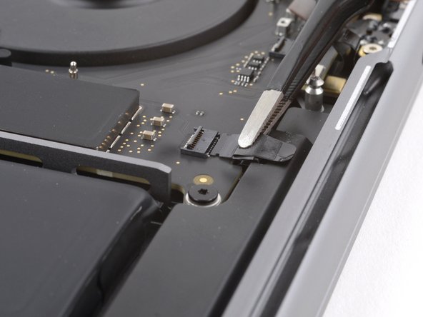
- Use the point of your spudger to pry up and disconnect the touch ID press connector.
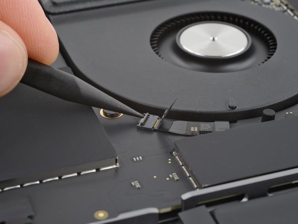
- Use tweezers to peel back the tape covering the microphone ZIF connector to the right of the fan.
- Use the point of your spudger to flip up the locking flap on the head of the connector.
- Use your tweezers to grab the neck of the cable and slide it straight out of its socket to disconnect it.
- Peel back the tape covering the left speaker ZIF connector on the right side of the logic board.
- Flip up the locking flap on the head of the connector.
- Slide the cable straight out of its socket to disconnect it.
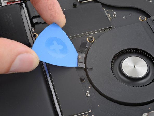
- The fan cable is adhered to the logic board. To avoid damaging the socket or cable, you'll unlatch the ZIF connector before separating the adhesive.
- Peel back the tape covering the fan ZIF connector.
- Flip up the small locking flap on the head of the connector.
- Slide the tip of an opening pick under the fan cable to separate the adhesive securing it to the logic board.
- Slide the fan connector straight out of its socket to disconnect it.
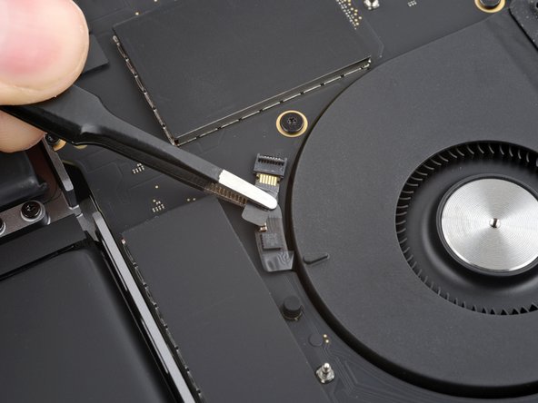
- Peel back the tape covering the right speaker ZIF connector on the left side of the logic board.
- Flip up the locking flap on the head of the connector.
- Slide the cable straight out of its socket to disconnect it.
- Peel back the tape covering the keyboard connector to the right of the main battery connector.
- Use an opening tool or a clean fingernail to flip up the locking flap on the head of the keyboard connector.
- Slide the keyboard connector straight out of its socket to disconnect it.
- Peel back the tape covering the keyboard backlight connector to the right of the keyboard connector.
- Flip up the locking flap on the head of the connector.
- Slide the connector straight out of its socket to disconnect it.
- Use a T6 Torx driver to remove the three screws along the top and left edges:
- Two 4.6 mm-long screws
- One 5.6 mm-long screw
- Use your 5IP Torx Plus driver to remove the eight screws along the right edge, bottom edge, and fan:
- Two 3.8 mm-long screws with silver screw heads
- Two 3.7 mm-long screws with small, black screw heads
- Two 5.1 mm-long screws
- Two 3.6 mm-long screws along the left edge of the fan
- Use your 3IP Torx Plus driver to remove the two 3.7 mm-long screws securing the middle of the logic board.
- Gently fold the right-side cables upright so they don't catch on the logic board in the next steps.
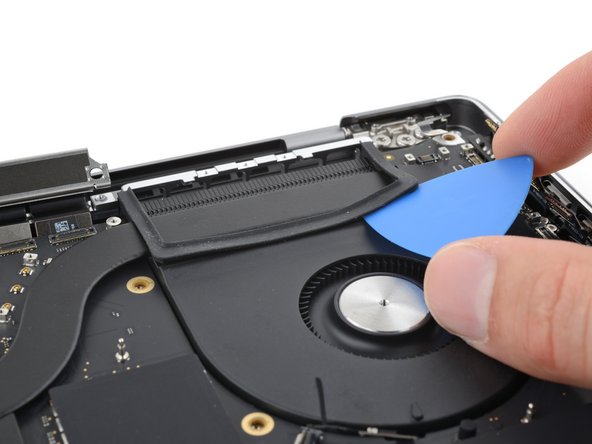
- A rubber gasket lays over the fan and heatsink and is secured with mild adhesive.
- Slide an opening pick between the fan and the rubber gasket to separate its adhesive.
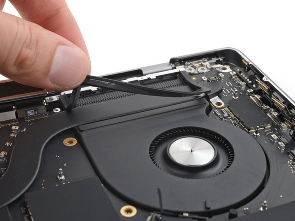
- Peel the gasket away from the fan.
- The gasket is still connected to the heatsink. Leave it in place for now.
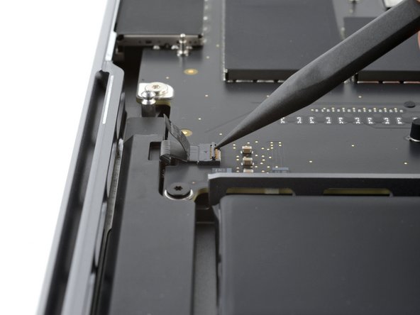
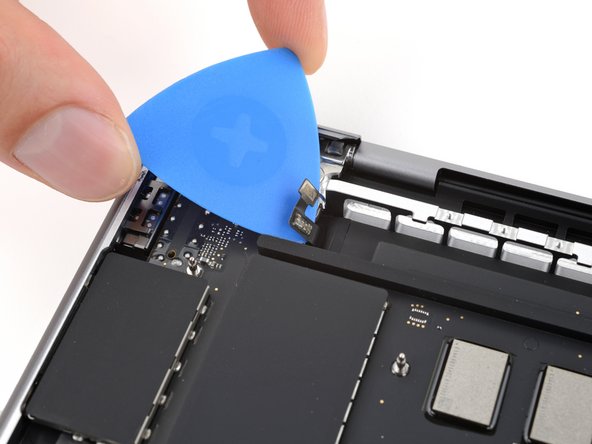
- Insert your opening pick between the left edge of the touch ID sensor cable and the logic board to separate its adhesive.
- Be careful not to snag the logic board on any of the eight cables on the right side of the frame.
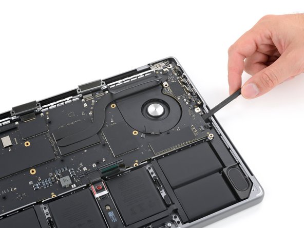
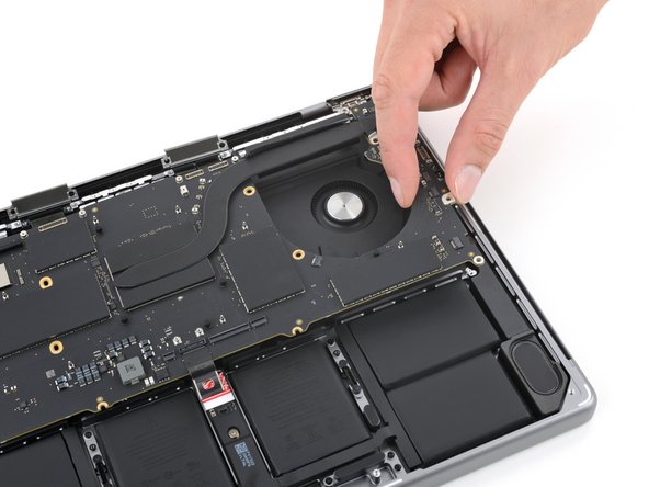
- Insert your spudger between the right edge of the logic board and the frame.
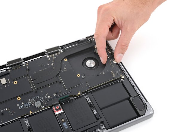
- Pry up until you can grab the logic board with your fingers.
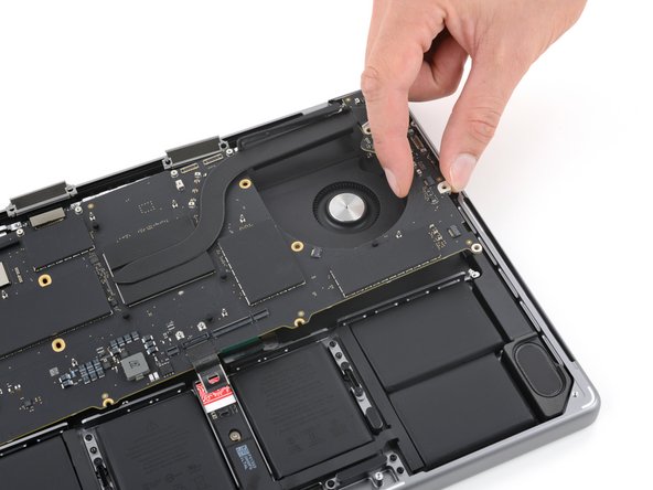
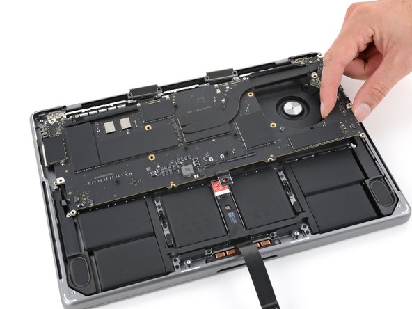
- Lift the logic board over the fan and shift it down slightly.
- This helps free the ports along the left side from the frame.
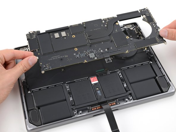
- Pull the logic board to the right to free the ports along the left side from the frame.
- Remove the logic board.
- During reassembly, make sure none of the 15 cables become trapped underneath as you lower the logic board into place.
- Use your spudger—or pieces of tape—to hold the cables out of the way.
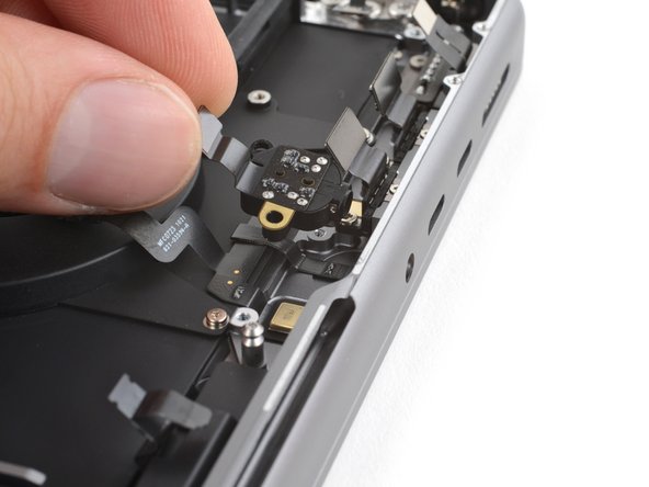
- Use your 5IP Torx Plus driver to remove the two screws securing the headphone jack:
- One 5.7 mm-long screw
- One 3.5 mm-long screw
- Remove the headphone jack.