Burned out driver repair in Led Ceiling Light LS24A8X-BPBC, 52 V driver.
ID: 167995
Description:
Steps:
- LED Kitchen ceiling light stopped working, it is verified that 230 V is reaching the power input (Red Electrical of Spain).
- Introduction; in 95% of failures of this type, the faulty element is the driver, not the LEDs. (LEDs are advertised to last for years... but the drivers are not touted in this way)
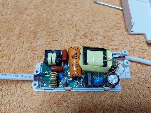
- Disassembly of the constant current driver (Be Careful it is not a DC output power supply, it is a Driver that regulates and adjusts the output voltage according to a fixed intensity that must always flow, so the voltage varies without or with a load connected.)
- We see the characteristic soot of an electrical flash burn inside the plastic casing, so we checked the corresponding area, using an LED flashlight, to see and follow the the copper traces.
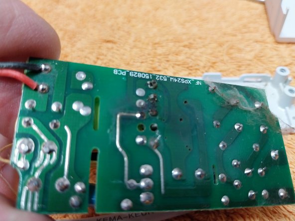
- Using a wire brush, clean as needed preparatory to re-soldering.
- The usual problem is overheating and wear on the electrolytic capacitor. Cut one lead to enable testing it without removing it from the PCB.
- Rating of the capacitor: 22 uF, it measures 21.8 uF, it is in perfect condition, this has been ruled out as a cause of the failure. It's lead is re-soldered.
- The next part under suspicion is the resistor or 'Fuse function resistor' in this case it is 5.1 ohms.
- The connection point of the resistor is found on the traces and de-soldered. I already re-soldered the joints that caused the flash, as seen in photo 1 above.
- I measured the resistance, it is open, burnt, it is 5.6 ohms, so I look in the 'disaster' drawer for an equal or equivalent resistor, I find 5.9 ohms.
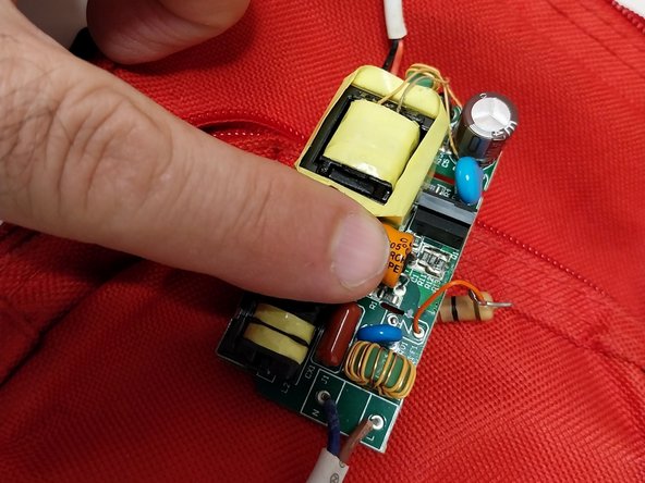
- The available resistor is at greater power and a slightly higher value, but it works perfectly. It is positioned and soldered.
- Since one of the leads is too short, I lengthen it with a piece of wire.
- Clean the burned area with a scouring pad or sandpaper. Let's recall that charred parts of any plastic or insulator, due to the presence of carbon, can become conductive, so it is best we clean this area.
- I attached a temporary power cable so I could test the ceiling light on the table. It initially turns on.
- As supplemental information; always useful for future repairs, I check the DC output voltages of the driver.
- Photo 1: Output voltage under load, ceiling light on.
- Photo 2 and 3: Output voltage with driver under no load 'Voltage triggered'. Very typical in drivers.
- To test the ceiling light, I leave it on for three hours.
- But it doesn't pass the test, when I perform a quick on and off test, eight in a row, the fuse resistor blows again.
- I then replace it with a 10 ohm 2 W one.
- With the new resistor, I leave it on again for one hour, disconnect and check the temperature of:
- Photo 1: Capacitor.
- Photo 2: Fuse resistor.
- Photo 3: Temperature of various points of the PCB, in no case was it high.
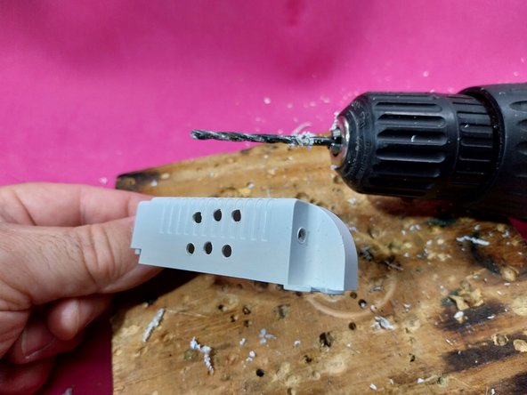
- Since both the capacitor and the fuse resistor tend to heat up a bit, I drilled three mm ventilation holes in the case.
- Photos of the drill holes (and drill)
- Another test with another resistor also did not bear fruit. It burned out under the rapid on and off test, so finally, the largest resistor, 47 ohms 2 W, was installed.
- This is the resistor that finally passes the tests:
- 47 ohms 2 W Yellow, Violet, Black, Gold.
- I soldered it properly on the PCB.
- Reassemble the case and covers.
- Final test, I leave the ceiling light on for one hour.
- Then I perform the eight quick turns on and off in a row, it works correctly.