Abask J05 Motherboard Replacement
ID: 168040
Description: This is a step-by-step guide to replace the...
Steps:
- Gently press on the SD card with a fingernail until it clicks.
- Release, then remove the card.
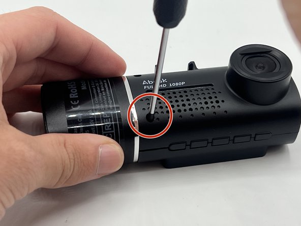
- Remove the 5 mm screw from the side of the device next to the suction cup dock with a Phillips #00 screwdriver.
- Remove the two 8 mm screws from opposite sides of the screen with a Phillips #00 precision screwdriver.
- Gently lift the screen.
- Push up on the interior camera portion of the device. It should pop out of the socket. Being careful to keep the wires attached, set it to the side.
- Reach into the device with a spudger to release the top two snap joints keeping the end cap attached one at a time until the front face lifts off.
- Be careful not to touch the screen.
- Repeat the process with the two remaining snap joints.
- Remove the two 7 mm screws on the side of the motherboard with a Phillips #00 screwdriver.
- Slowly pull up on each corner of the motherboard, stopping when the corner pops loose of the anchor.
- Repeat the process with each corner before slowly pulling up on the board to detach the glue on the underside.
- Carefully flip over the motherboard, being mindful of the wires.
- Remove the two 5mm screws on the underside of the motherboard with a Phillips #000 screwdriver.
- Follow the golden ribbon from the screen to the screen dock. Push the two small black stubs on either side of the dock away from the dock until it pops loose.
- Remove the ribbon and the small plastic piece from the dock.
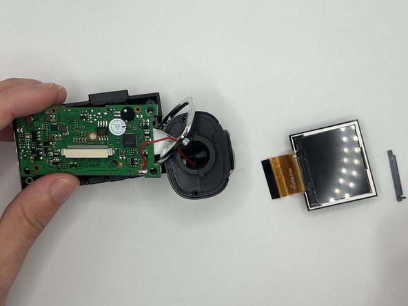
- Gently pull up on each corner of the white screen piece until the adhesive comes loose.
- Remove the screen fully from its holder.
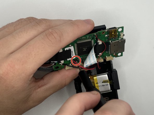
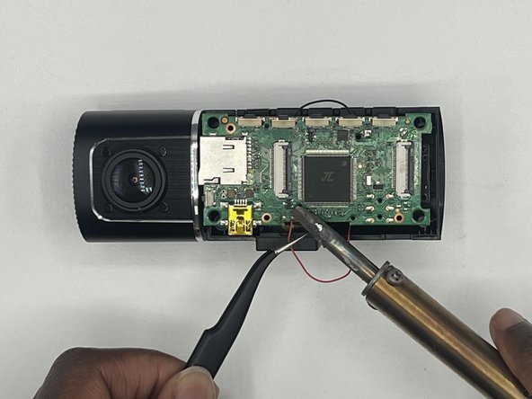
- Desolder the red wire attached to the motherboard.
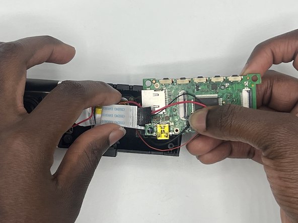
- Detach the ribbon cable connecting the motherboard to the rest of the device.
- Desolder all four wires connected to the motherboard.
- Remove the motherboard from the device.